Designing the Kincaid Arcade Vector Graphics Card
How I, as a 16-17 year old, began to design my own vector arcade system from the ground up.
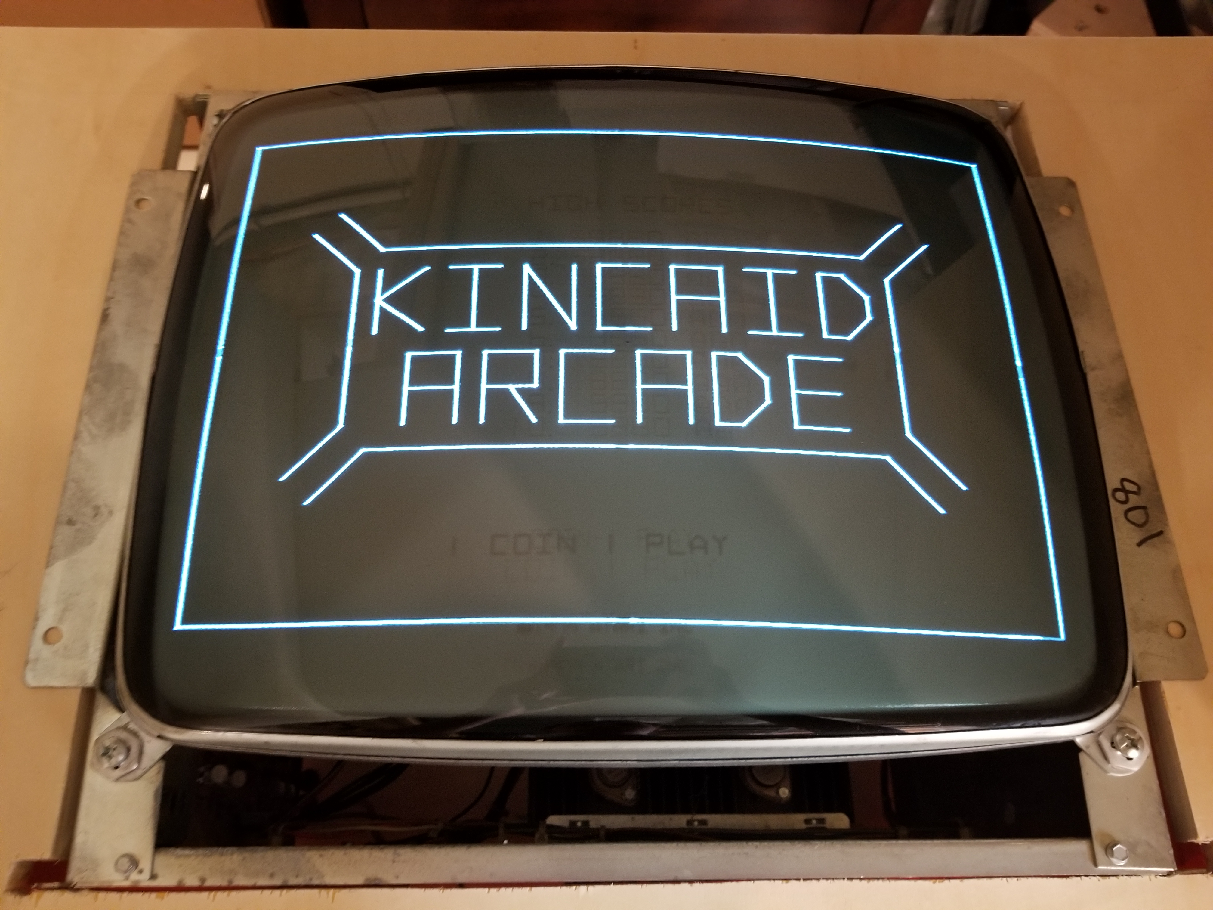
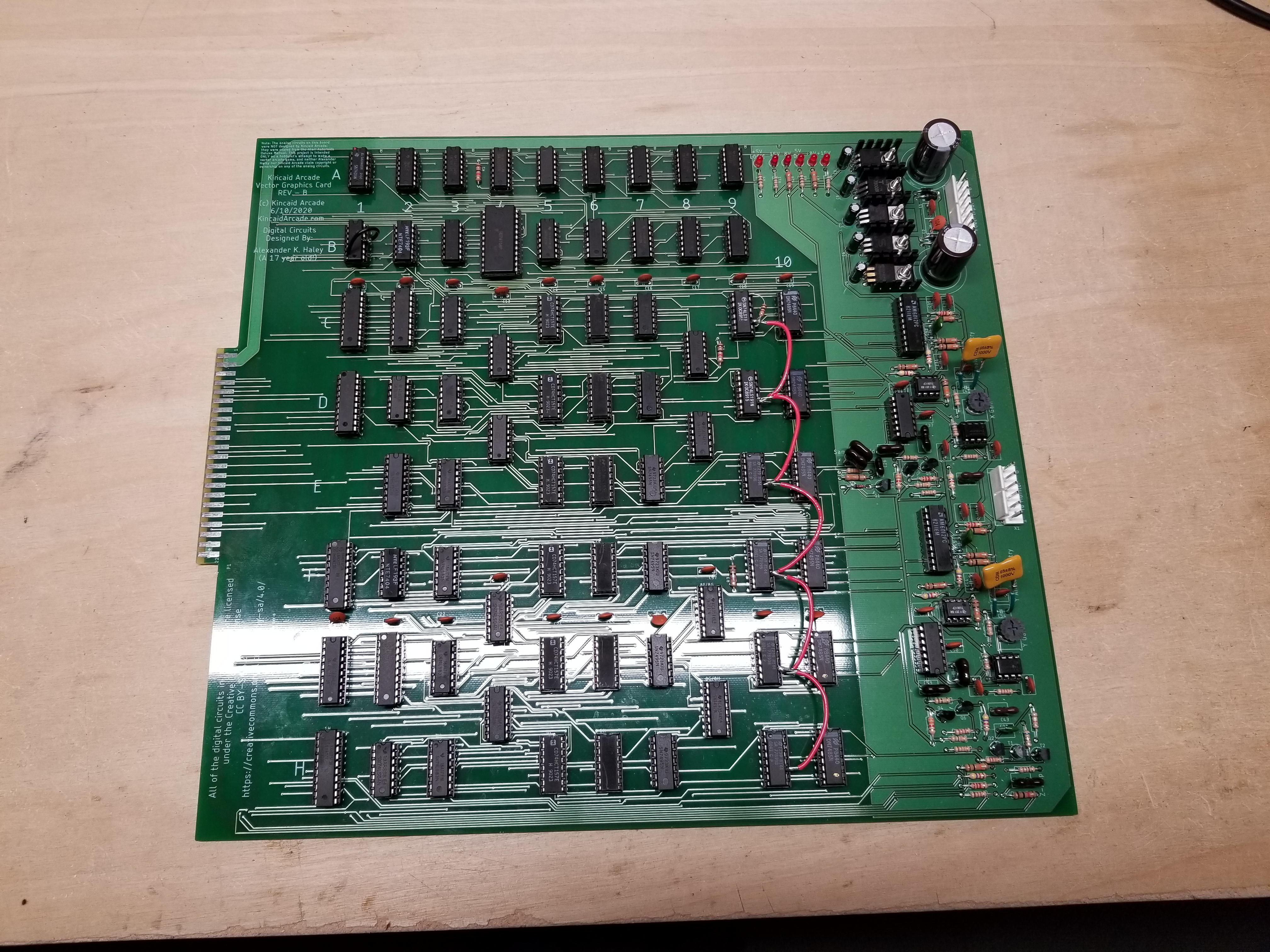
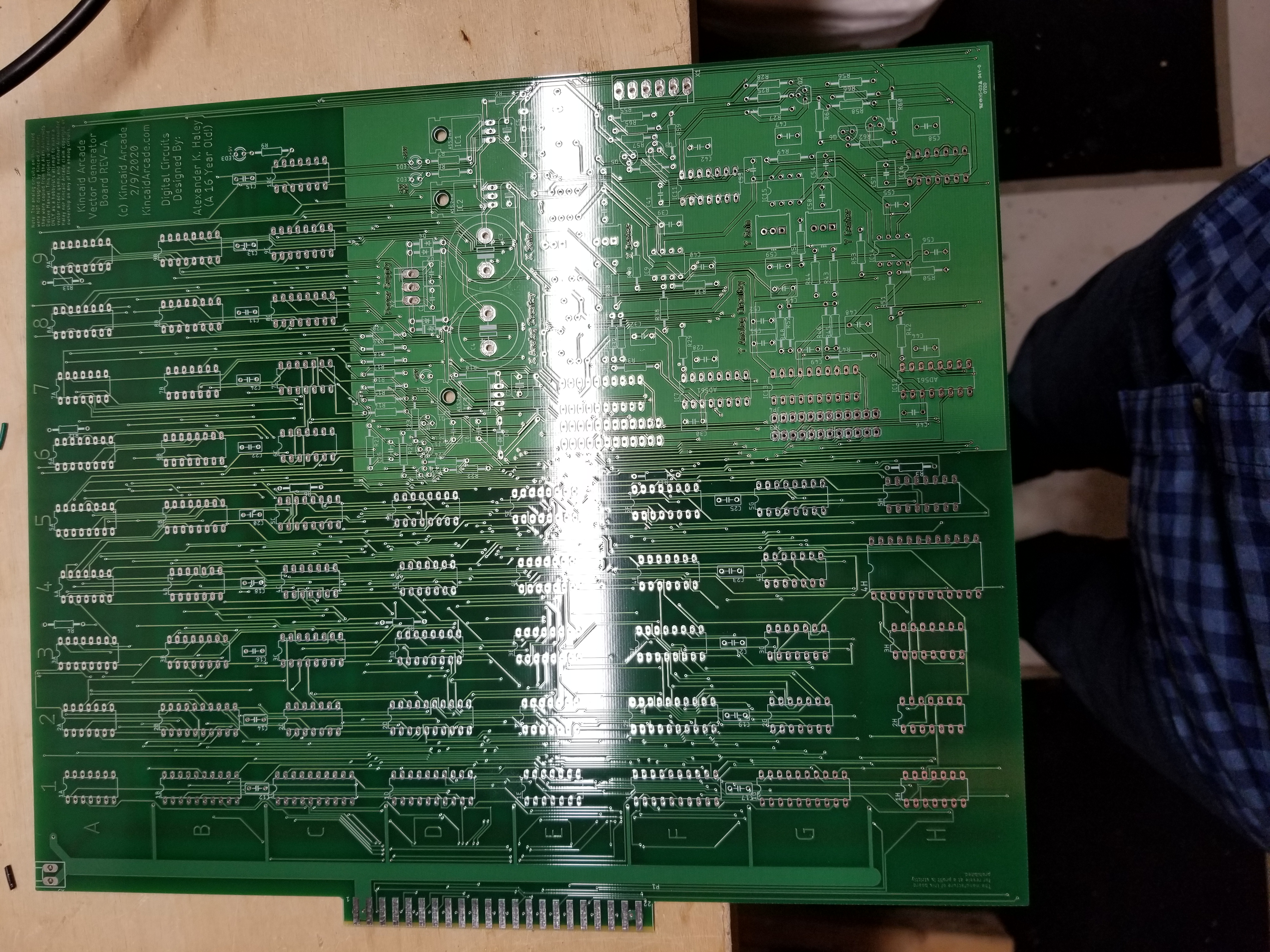
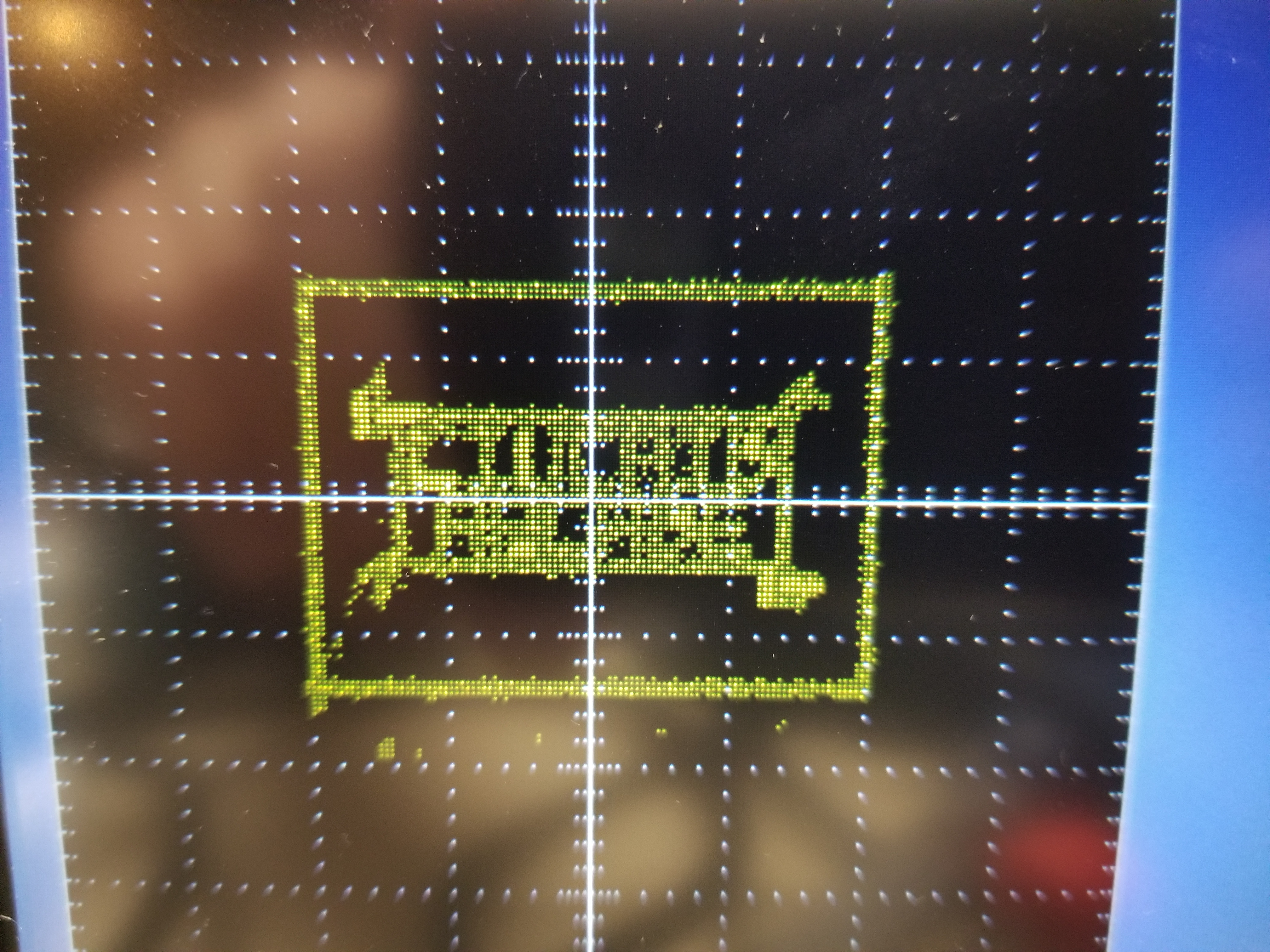
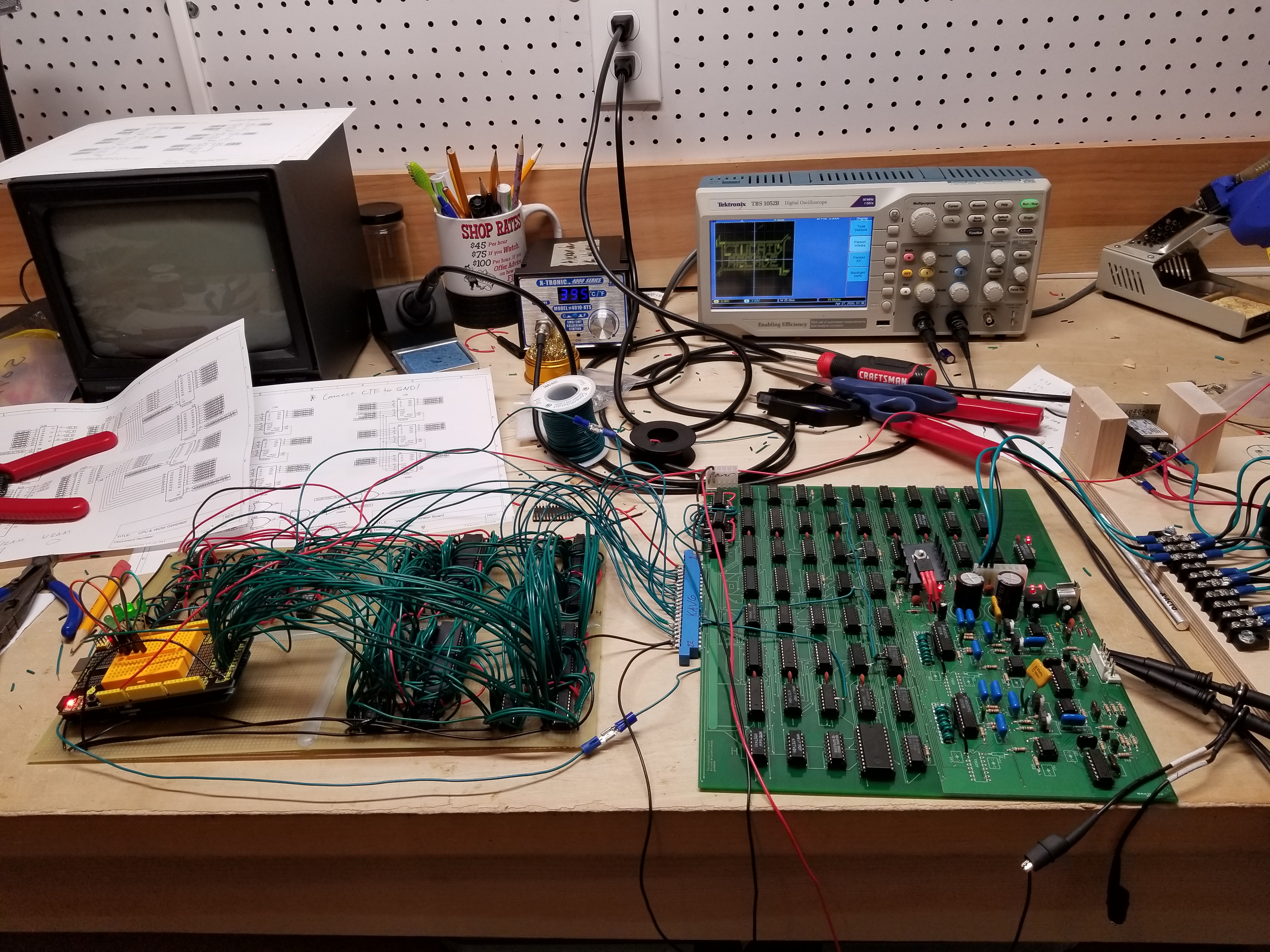
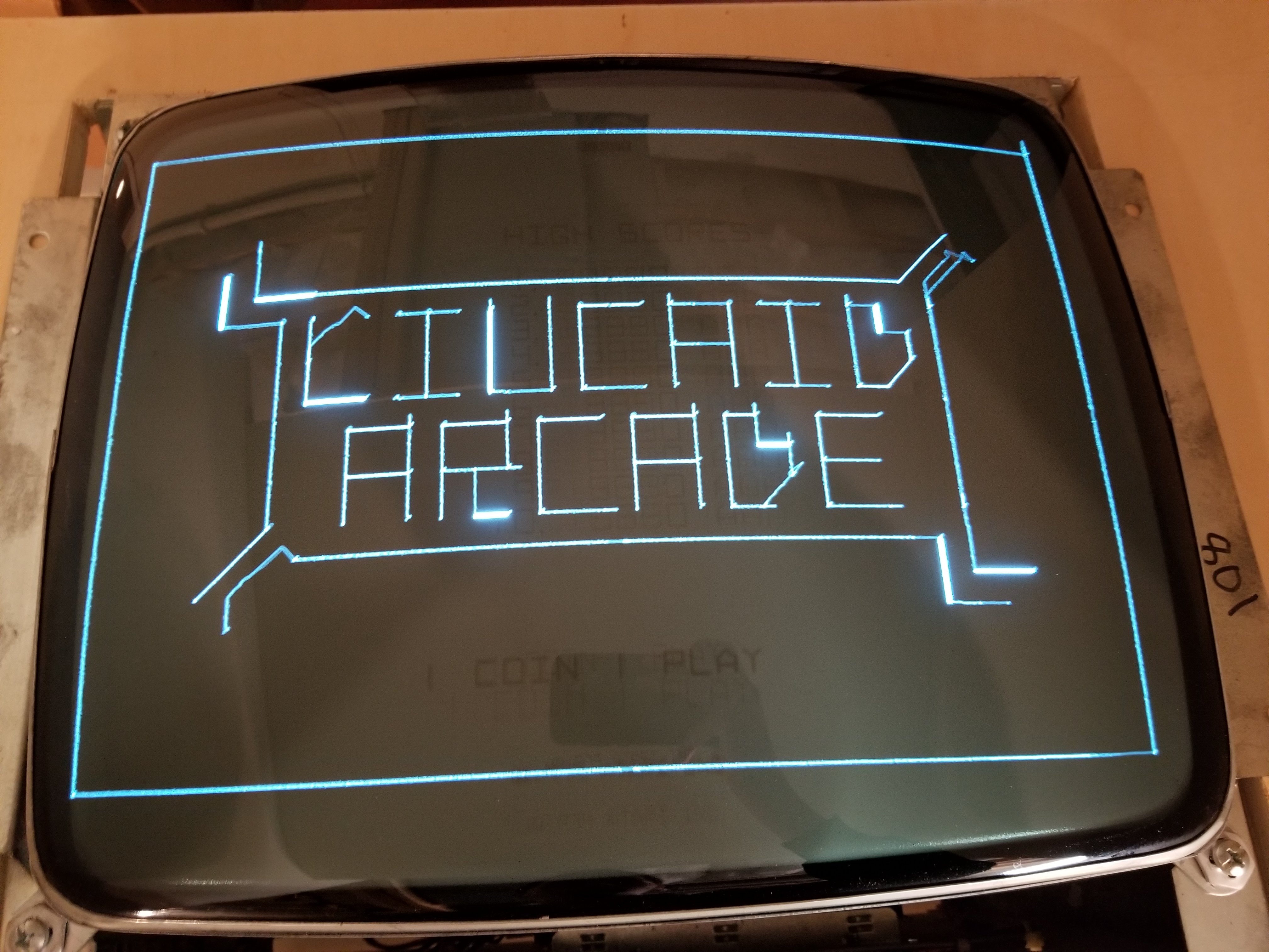
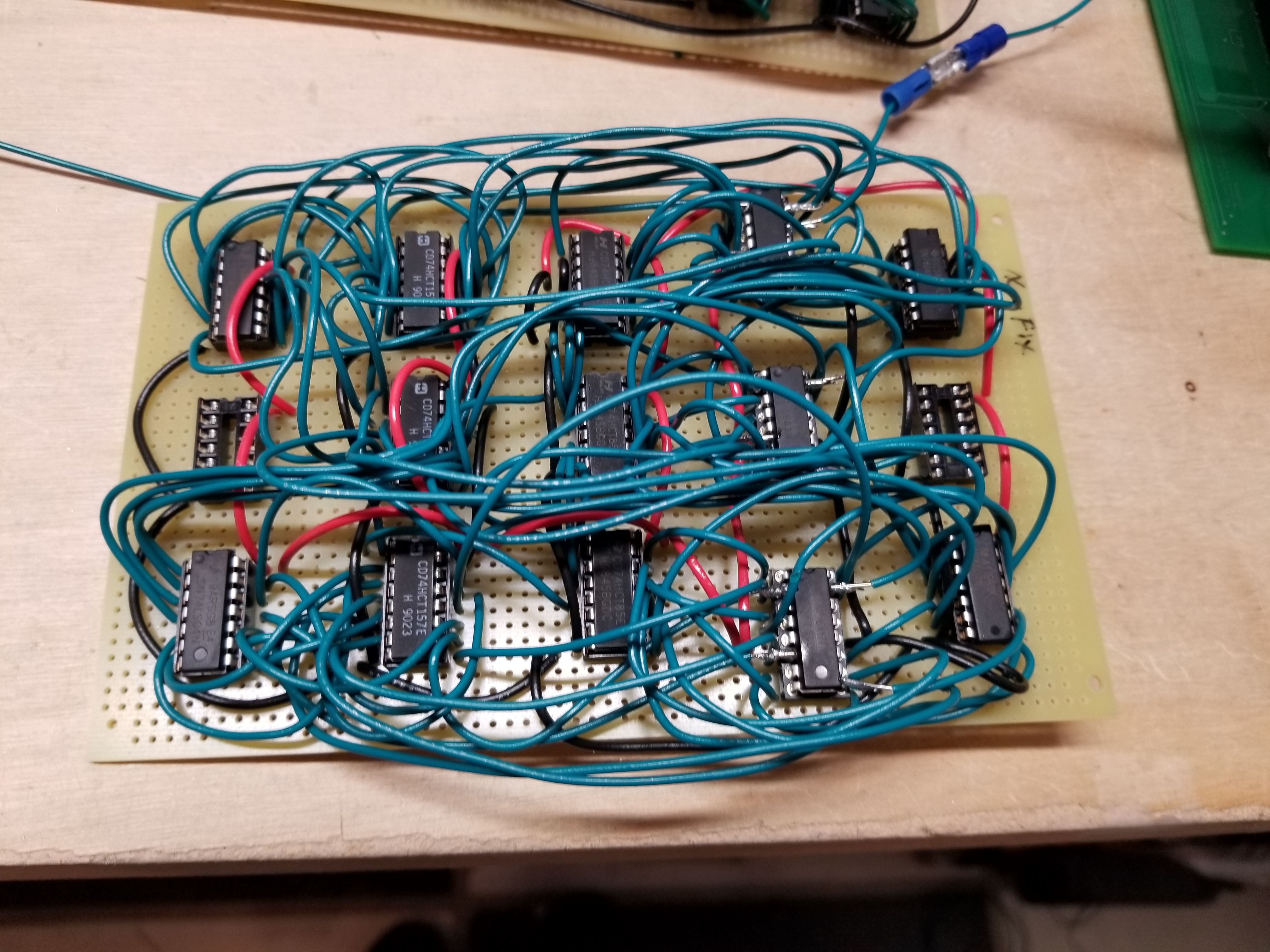
Top: The graphics card drawing a test image on a G05-801 at 186 frames per second. Bottom: The graphics card.
About This Project
This was my school project for the year of 2019/2020. I had always wanted to be able to count myself among the few designers who released a vector arcade game, so I figured this would be a fun project. After spending approximately 326 hours and 10 minutes working on it, I have a vector graphics card that can normalize xy coordinates and draw the resulting line on the monitor.
I was originally planning on doing a 16 bit processor and a video game program for it as well, but unfortunately, I was a little bit over-optimistic on the amount of time that would require. I also still have to finish Golden Spike, and my parents thought that it would be good if I just did a really simple project for my last year before college. Hopefully, I'll revisit this project after college and finish designing my vector arcade system.
If anybody is wanting to make their own vector game, I have released all of the design files on my Downloads page so that you won't have to spend as much time trying to figure out the hardware portion of things like I did. I am even okay with it if a Klovver decides to do a run of my graphics cards and sells them for a profit. I just ask that you give me the credit due for designing it, in accordance with the CC BY-SA 4.0 license. Have fun!
How it Started
This project started the same way almost all of my other projects started. I asked myself what I was going to do for my school project this year. I had a list of more than 20 things that I thought would be interesting to do. One of them was to design my own computer -- make a processor out of TTL logic and write a text-based operating system for it. The more I looked over the list, the more the project appealed to me. However, I began to think about what I would do with it after I made it. Making text files didn't sound very appealing. The more I though about it, the more I realized the only way something like this would have any use after the school exposition would be to write a game for it.
I figured I'd need to design myself a processor with a 32 x 32 character field and the ability to do a couple of motion objects, all read out of a graphics ROM. That sounded simple enough. Unfortunately, I could not come up with a good original game for it. I came up with plenty of complex games, but they would need the capability to do loads of motion objects, and therefore have loads of chips on the board. Since I was hoping to make this an "easy" project, I was a bit discouraged.
Several weeks later, my Dad took me to Funspot. I was thinking about the Star Castle game there and it occured to me that I could design my own processor for a vector game, just like Larry Rosenthal did. Now THAT sounded really fun. I explained my project idea to my parents, and they thought it was a good idea. So, I started doing research on processor design.
Why I Decided I Needed a Graphics Card
I will admit, this is nowhere near the "small" or "easy" project I hoped to do this year. Raster stuff is easy; vector is a whole different animal. I was staring a pretty big project in the face with no real idea of what would be the best to tackle first. I had come up with an original idea for what I thought would be a "hit game", but it would require drawing loads of vectors at all different spots of the screen. The problem with this is that vector monitors are limited by the total length of the lines drawn in the frame, and that includes lines drawn with zero brightness (like when it moves between objects).
I was also doing research on the ways that various companies approached doing vector games. From what I could tell, there were two main methods of processing the vectors to put on the screen. There was the Atari method, as described by Jed Margolin, which involved loading the game images into a ROM and drawing them on the screen. This freed up program runtime but limited what could be drawn. The other method was how Larry Rosenthal designed his VECTORBEAM hardware. Every vector was calculated during program runtime, which allowed great freedom in what could be drawn, but also took up pretty much all of the processing time each frame.
From what I could tell, neither method would be capable of doing the game I wanted, since it involved me needing to rotate lots of tiny fighters and draw lots of long lines for the massive capital ships all in a single frame. I figured one way around this would be to store all the vectors in a double-buffered bank of screen RAM. But I'd still lose most of my program runtime doing calculations and loading them into RAM. I was reading about the Atari Vector Generator in Jed Margolin's article The Secret Life of Vector Generators, and he described how Atari did "Binary Normalization" in their analog vector generators and the pre-calculated images for the digital vector generators. I realized that I could design some TTL circuits that would be able to do the same thing. It would allow me to load the endpoints into the vector RAM and have some TTL circuits handle all of the math for calculating the slope and moving the beam between those two points. Something like that would be a very large design, so I figured I'd make it into a vector graphics card for my processor. Unfortunately, that would end up taking the entire year to do.
My First Vector Monitor
Before I get too ahead of myself, this project won't go anywhere without a Vector Monitor. I spent some time looking around Ebay and some other websites and found a suitible G05-801 on QuarterArcade.com. It was the ONLY monitor that was availible.
Here are some pictures of it when it arrived:
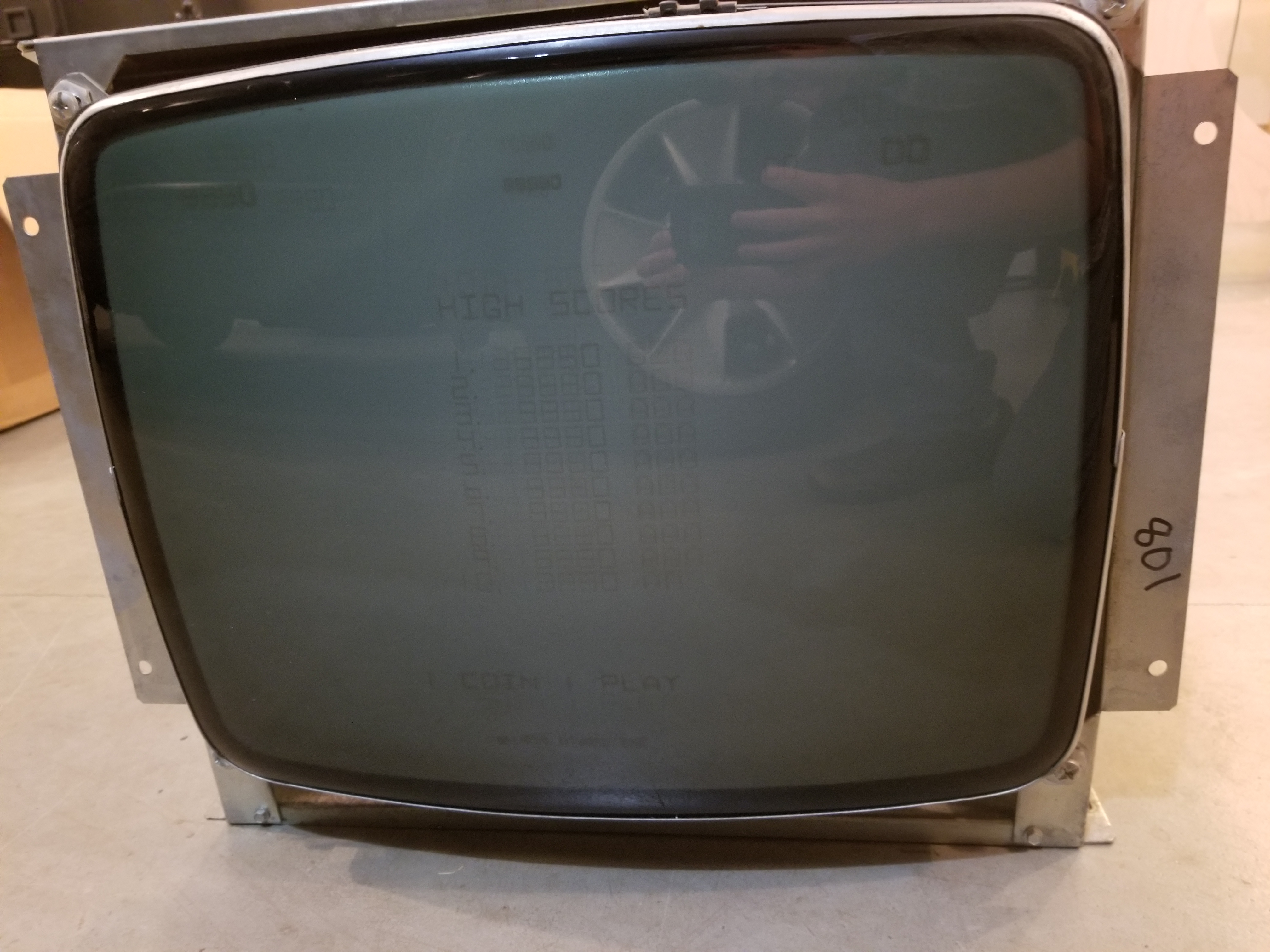


I was thankful to see that the monitor was packaged very well. I was also surprised to see that the monitor and I both share the same birthday. How cool is that!
The monitor iself was "untested", but my parents and I knew when we bought it that it would be a basket case and we would need to have somebody fix it. I remembered from going to the Pinball Wizard Arcade back when I was making Garden of Eden (for "research" purposes :) that Sarah St. John also had a repair business. We contacted her about having her fix the monitor, and she came up to take a look at it. She was blown away when she saw that I had done another homebrew pinball machine (Golden Spike) and that I was even collecting and fixing my own arcade games.
Anyway, we had her do whatever it would take to get the monitor bulletproofed so that I wouldn't lose lots of time from it going down while prototyping my circuits. She did an absolutely amazing job! In all the time I have had it running with my prototype hardware, it has not taken a dive at all. She also gave me loads of useful advice with my project. The two most important things she told me were that I should always test the video output on my oscilloscope before hooking it up to the monitor (to make sure some vectors aren't overdriving the monitor), and that I should just get an old Asteroids transformer brick to supply the AC voltages for my game.
Prototyping
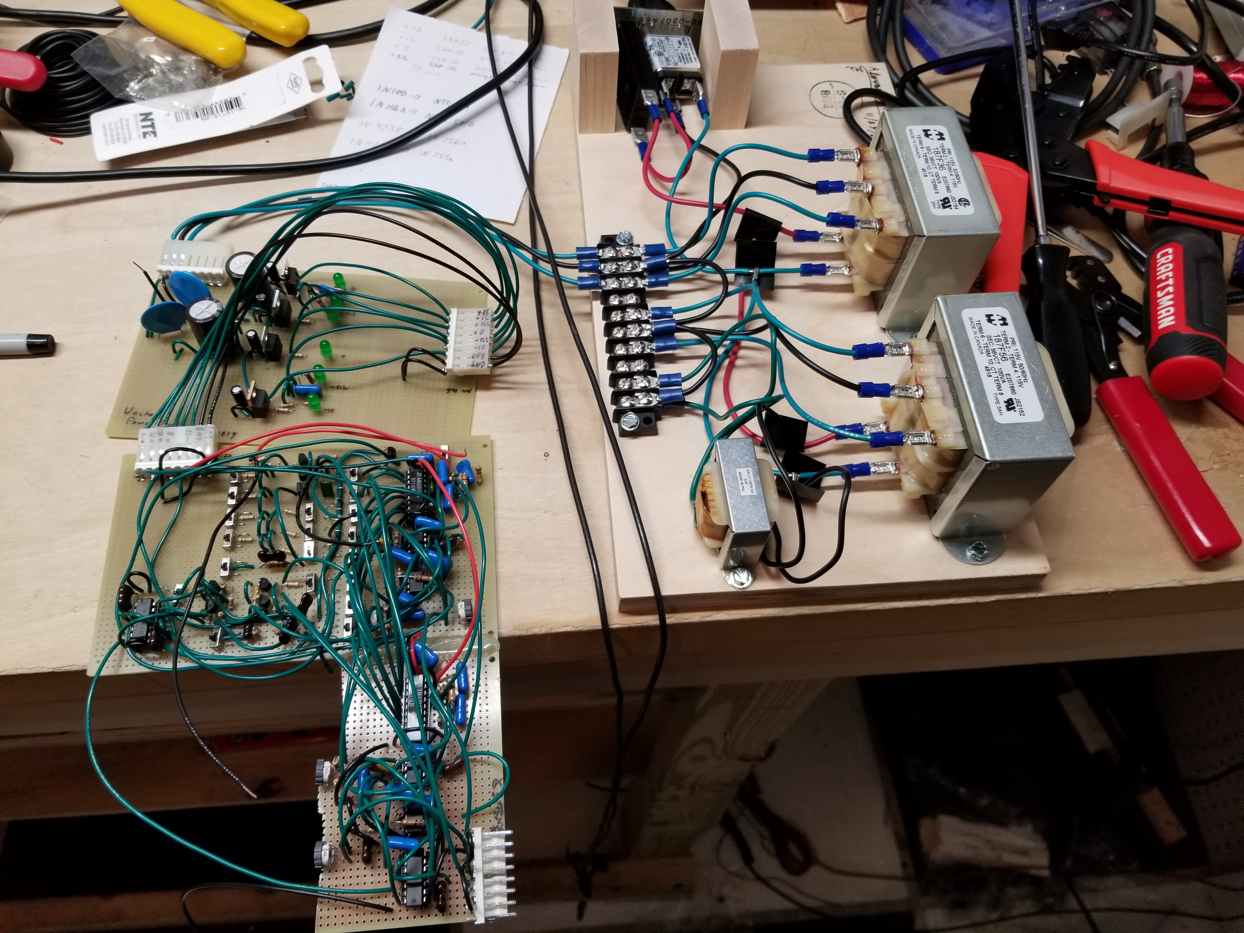
While my monitor was out for repair, I got to work on prototyping the vector generator. I didn't know anywhere near enough about analog to design my own, so I copied the Digital Vector Generator out of the Atari Asteroids Deluxe manual. I designed everything else myself. First things first, I wired up a test rig with some center-tapped transformers and began to prototype the power supply for the analog section.
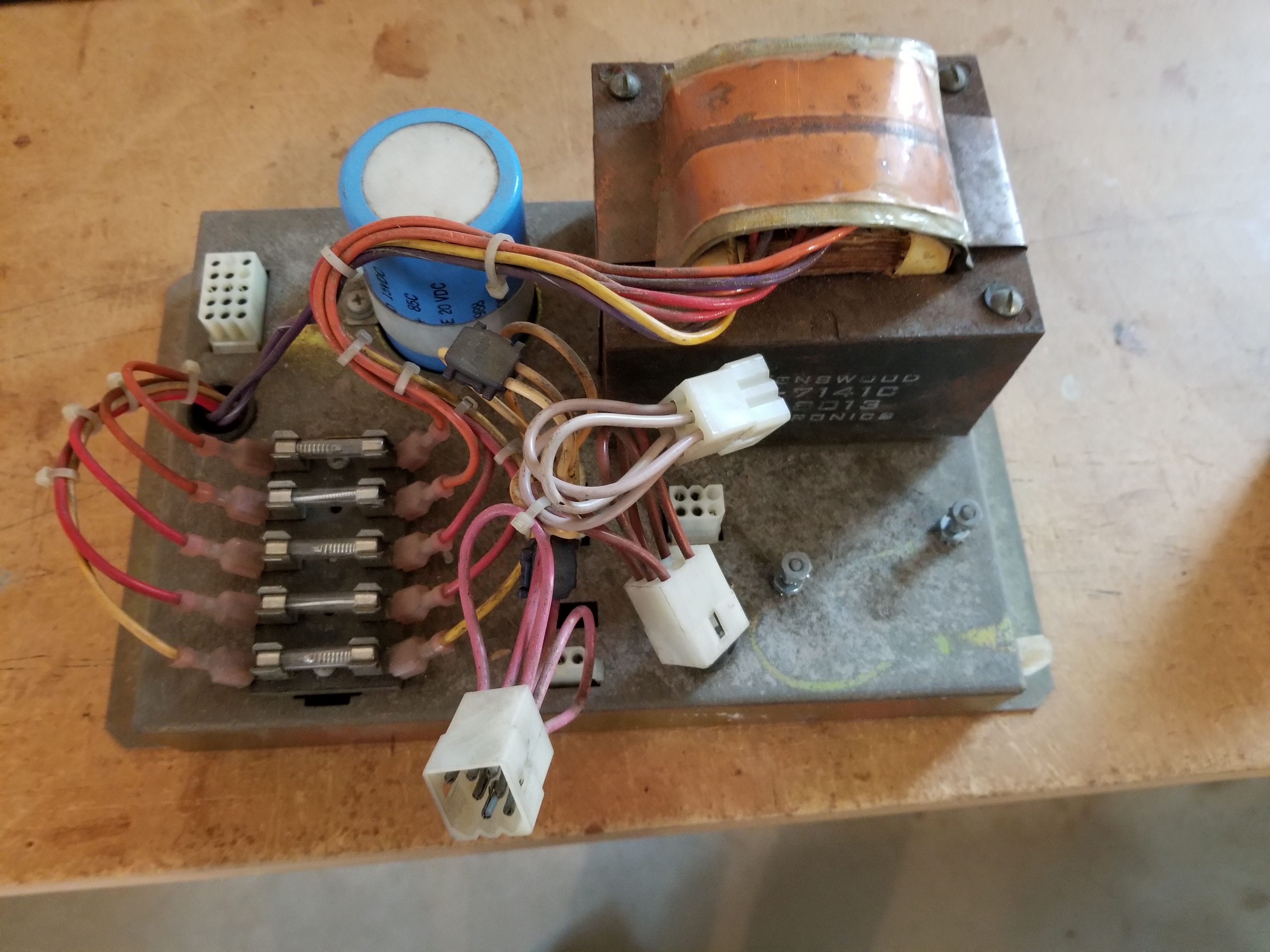
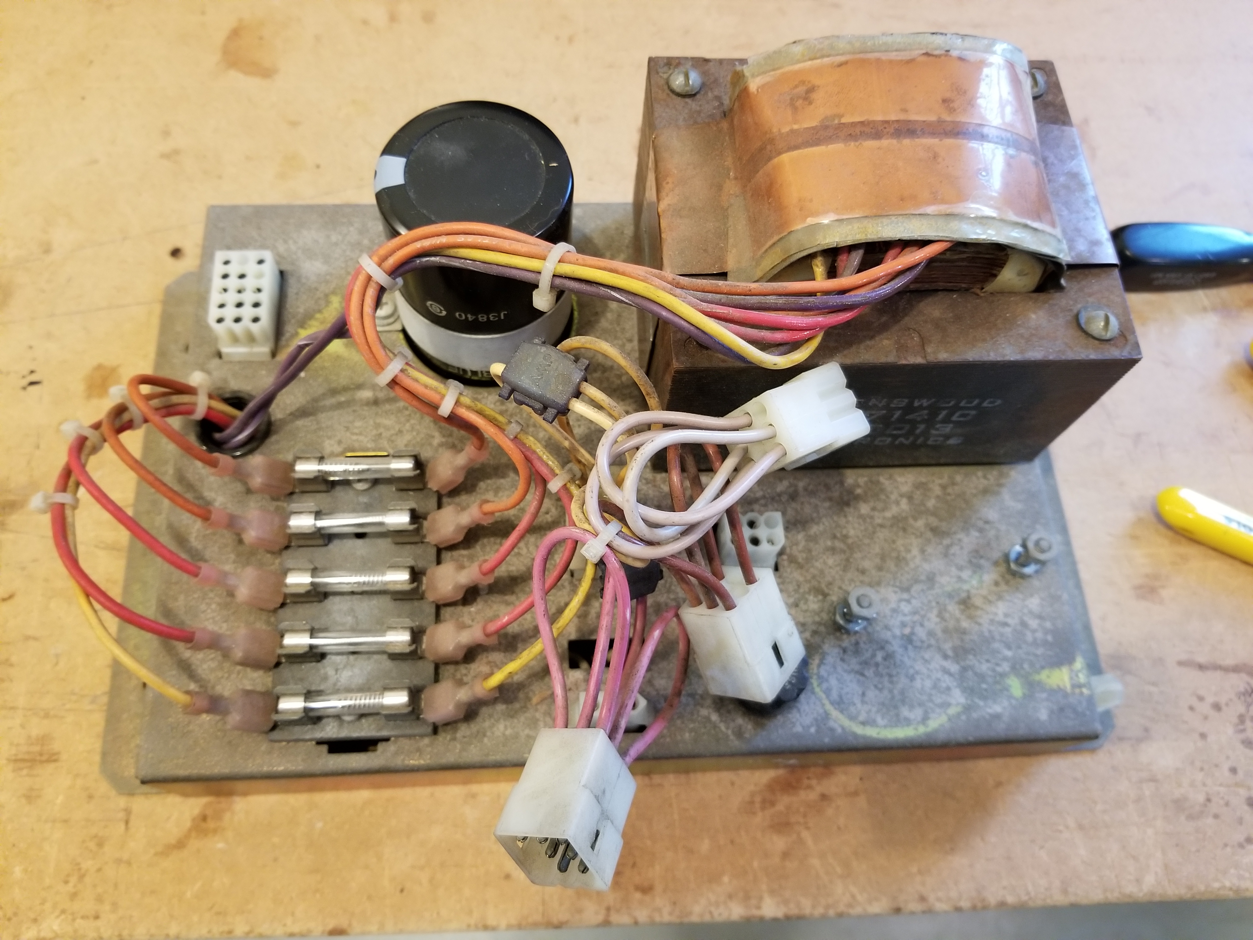
The transformer board. I was originally going to use this to power the monitor as well.
I watched a talk Larry Rosenthal gave about his time with video games and he mentioned that the first time you power on an analog circuit is the "smoke test". I agree, 100%
I put a capacitor in backward and it vented. The video was taken after I unplugged it... it does no justice to the funnel of acrid smoke that ran for the 30 seconds I wasn't brave enough to reach around and unplug it... This is why you pay extra to get capacitors that vent. Imagine what would've happened if the capacitor had exploded instead...
After that fiasco, I put a new capacitor in the correct way, and it worked just fine. I soldered up the regulators for the other voltages and added LEDs so I'd know at first glance if I screwed something up:
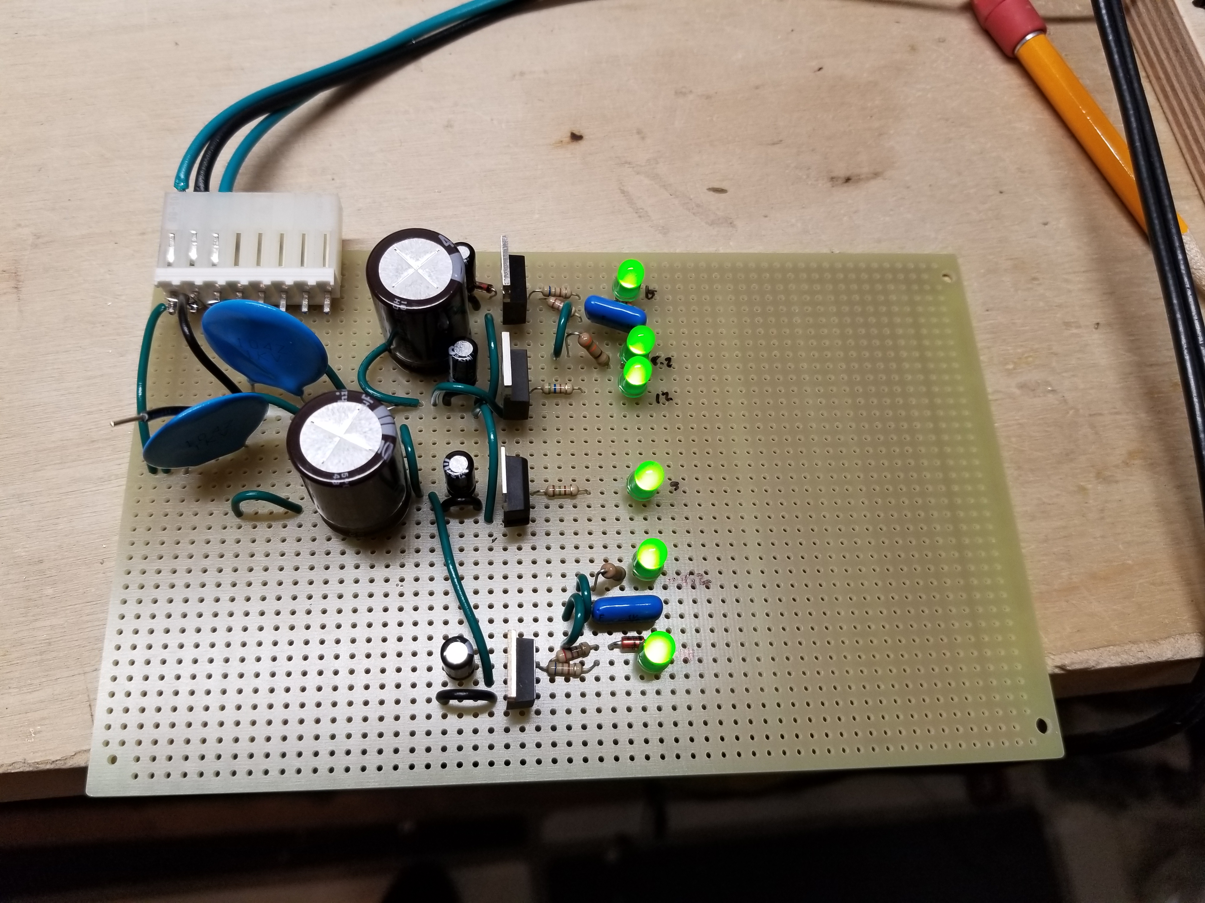
No smoke or flames :)
After soldering up the tiny power supply, I soldered up the circuits for one of the DACs. Since Atari had circuit layouts for both the AM6012 and the AD561, I chose the AM6012 because it was the cheaper part, and because it had 12 bits. I proceeded to solder up some switches to correspond to each of the 12 input bits so I could test it. Here's what it looked like:
One of the things that perplexed me at the time was why connecting the 2 most significant bits on the DAC to +5v would make the output swing to its maximum extent. After all, it was a 12 bit DAC, and if the first bit was HIGH, it should only swing to half of its range (the center). I realized later that Atari only wanted to use 10 of its bits, so they used resistors to bias the output so that the 2 most significant bits could just be tied to ground while the rest of the bits did everything else. I had no idea what parts to change so I never tried to change that. I also figured that a resolution of 4096 by 3072 would take my counters longer to move the beam across the screen. (Why didn't I just feed them a faster clock signal?).
After I verified that the output would move properly when I flipped switches, I soldered up the other DAC and tested it. It worked fine.
Now that I had my vector generators working, I had to design the digital circuitry that would drive them. After spending several hours on drawing them up, I started wondering how I was going to prototype them. The design wasn't the largest thing I'd done; it was only 50 chips, but that would still take loads of protoboards to make, and protoboards are expensive. I figured that perhaps it was time to learn how to wirewrap. I had read everywhere that wirewrapping was fast and cheap, so I thought it was a great alternative to those massive prototypes I'd do.
This is what my protoboard looked like when I set it up for wirewrapping:


(I was still waiting on some 74191s and 7497s at the time)
As I would soon discover, wirewrapping is actually pretty difficult. I didn't have a cut-strip-wrap bit, so each wire took me several minutes instead of several seconds. I also spent a lot of time trying to figure out why a group of 74191 counters weren't counting properly. As it turned out, my clock signal looked too much like a sine wave for it to work at 20MHZ. If I had known about schmitt triggers back then, I would've been able to fix that. Oh well.
At this point, I was making no progress in prototyping my circuits. I had also done the math and found that the cost of wirewrapping sockets was more than double that of the combined cost of regular sockets, perfboards, and wire for a comparably-sized prototype. Ooof. Trying to wirewrap this thing was a big mistake.
It was about this time that China locked down 10+ million people in Wuhan. The PCB manufacturer that I use, QuickTurnPCB, is located in South Korea, and we figured that whatever China had was going to spread to them pretty quickly. If it did, I wouldn't be able to get circuit boards made whenever I finished the prototype. So, we made a hasty decision to ditch all attempts to wirewrap it and just fabricated a circuit board. I figured I could just cut-and-jumper any issues with it.
That would be a bit optimistic.
Here were the boards when they arrived:
I wouldn't end up cleaning up my workbench until after I fixed Jet Fighter. It was pretty messy, which is why the boards were hanging off the edge of the table...
At any rate, I would give up on the electronics for a bit and work on the cabinet...
Designing the Cabinet
What is an arcade game without a cabinet? An ugly mess of wires and boards :)
In all seriousness, though, this thing needs a cabinet. There was no way that I was going to make something tiny like PERISCOPE. The game I was planning to make would be a two-player cooperative game, so it'd need space for two people to stand side-by-side. I also wanted to have the monitor reflect against a half-silvered mirror so I could give the game the illusion of being projected over a backdrop, like in Omega Race or Asteroids Deluxe.
Like always, I drew up my design in a modelling program:
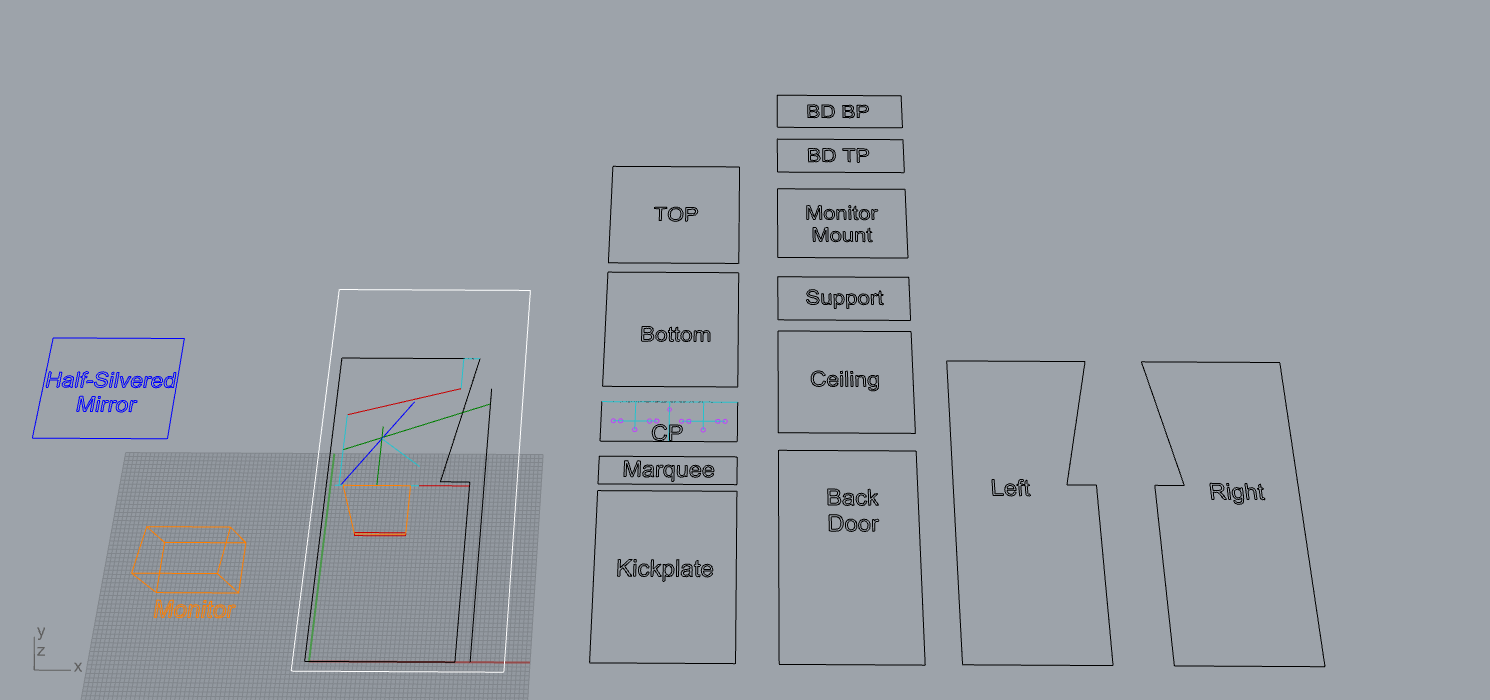
It is obvious that I took inspiration from the Vectorbeam cabinet designs. Unfortunately, I didn't do a very good job of designing where the monitor should go. In Asteroids Deluxe, the monitor is actually slightly under the control panel and pointing toward the back top of the cabinet. If I ever had to redesign this cabinet, I would make that change.
Anyway, we started by cutting out the cabinet pieces:


I had to have my dad use his hand router to cut out grooves for the cabinet pieces. From there, we glued 'em up:
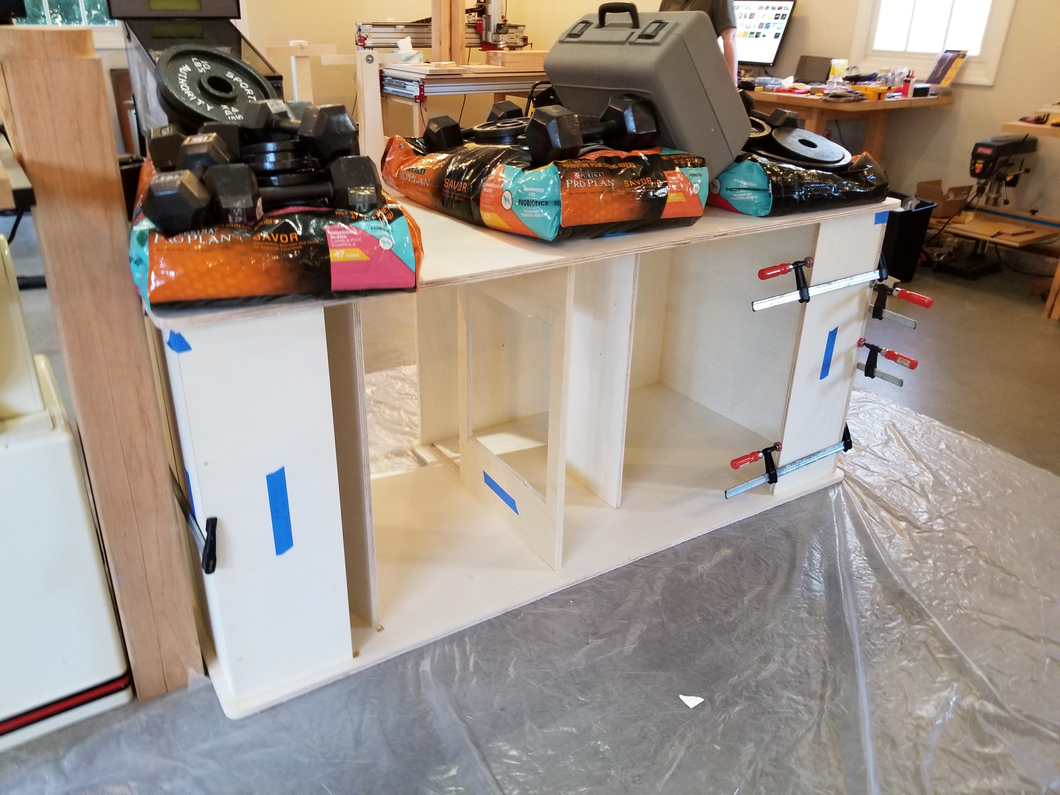
This is what the cabinet looked like after we glued it up:

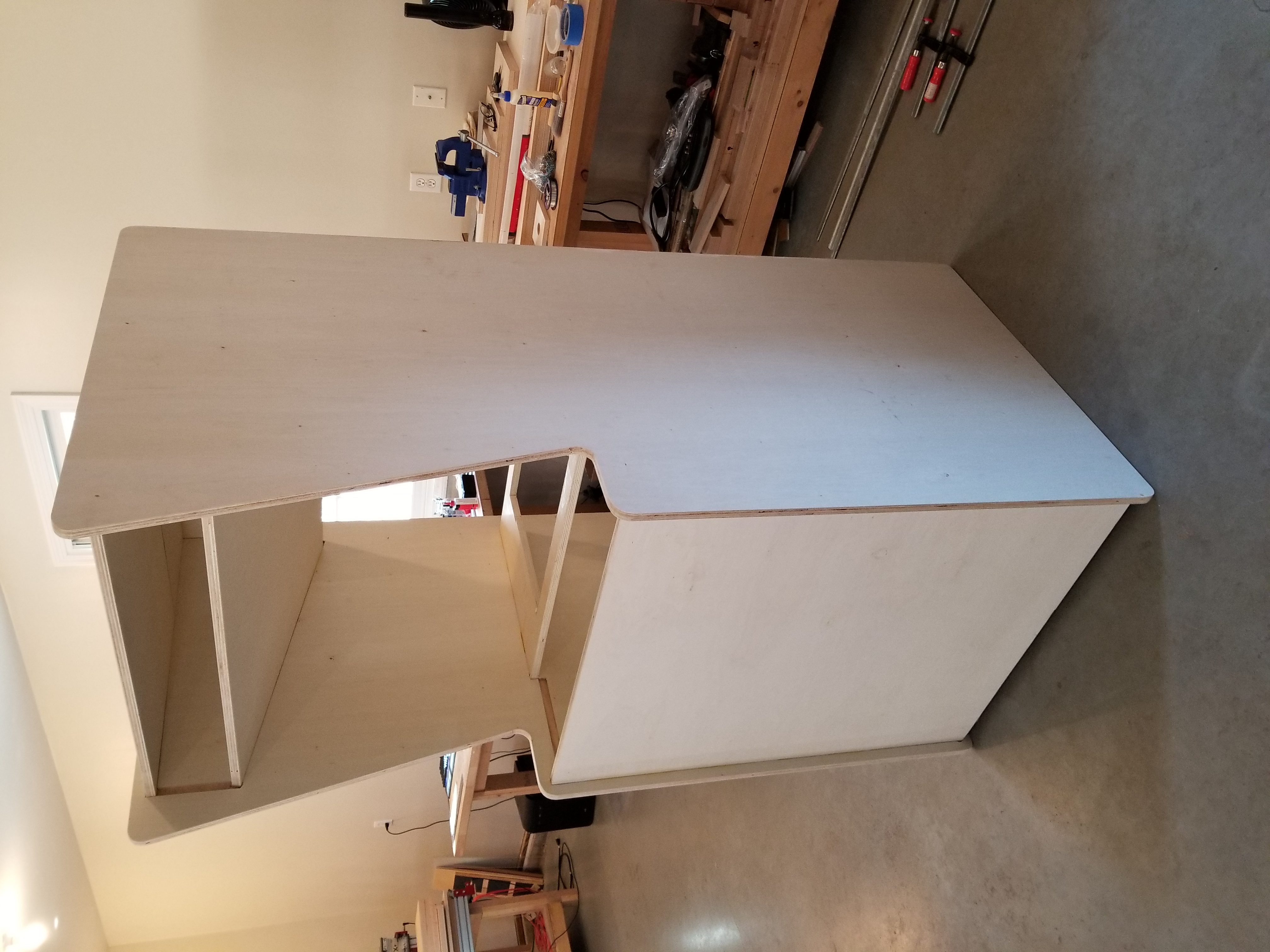
This cabinet is a bit of a beast at 34" wide by 34" deep by 70" tall. I was originally going to keep the dimensions close to that of WARRIOR (~68" tall by ~25" wide by ~26" deep), but my parents told me not to let vintage '70s precedent get in the way of being comfortably sized. So, I made the cabinet 34" wide. I think my parents actually encouraged me to make it 36" wide, but there are issues with that:
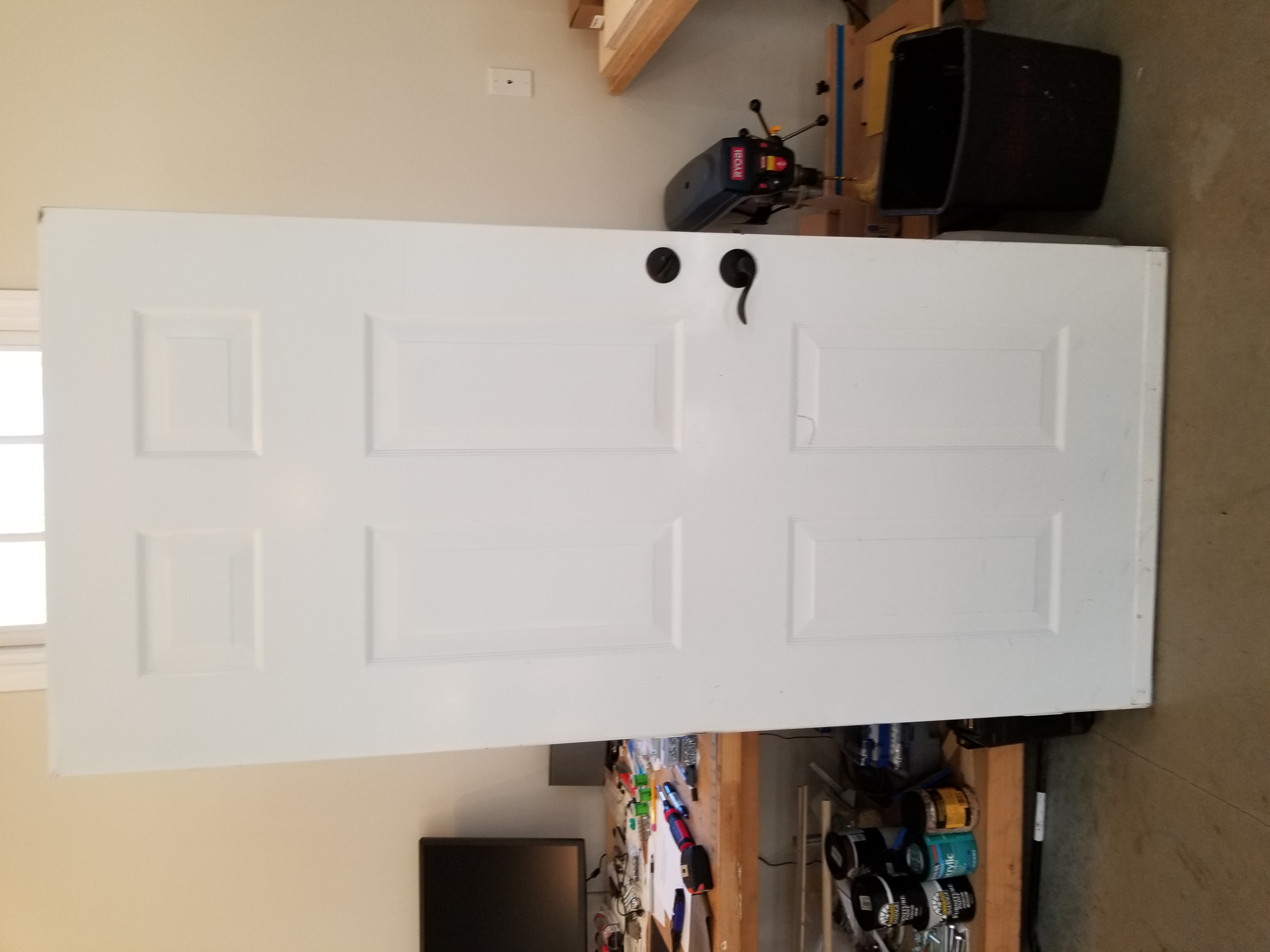
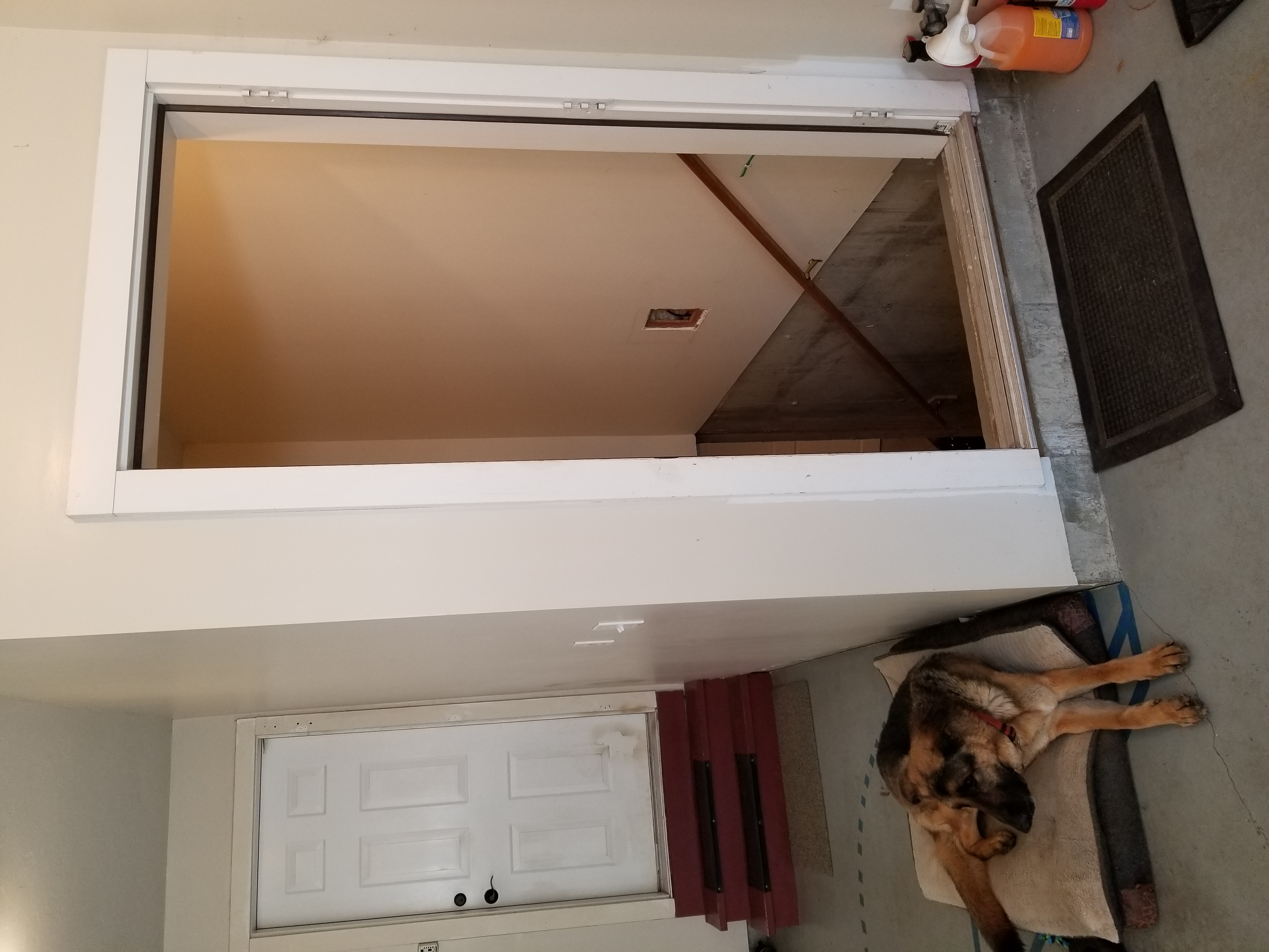
That's right: we had to pull the door off of its hinges to get it into my workroom. The doorway was only 35" wide without the door. Since the door was more than an inch thick... yeah. Also: Good boy, Lexington. :)
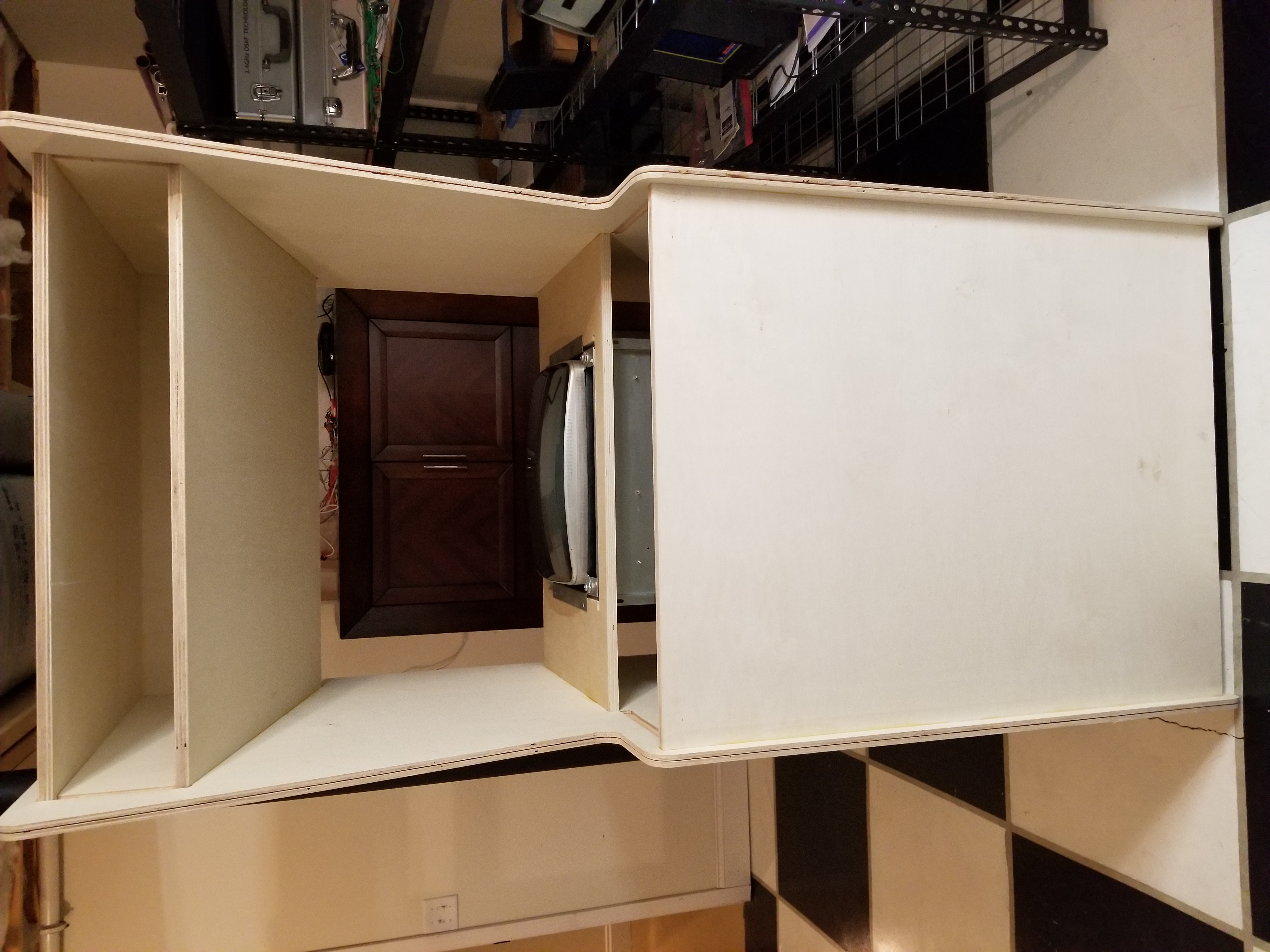
Here's the cabinet in the workroom, and how the monitor mounts in:
Fixing the Prototype Graphics Card
Remember that circuit board I had fabricated? Well, needless to say, it didn't work. That didn't stop me from holding on to the hope that it would.
It would take a lot of cut and jumpering to make it work.
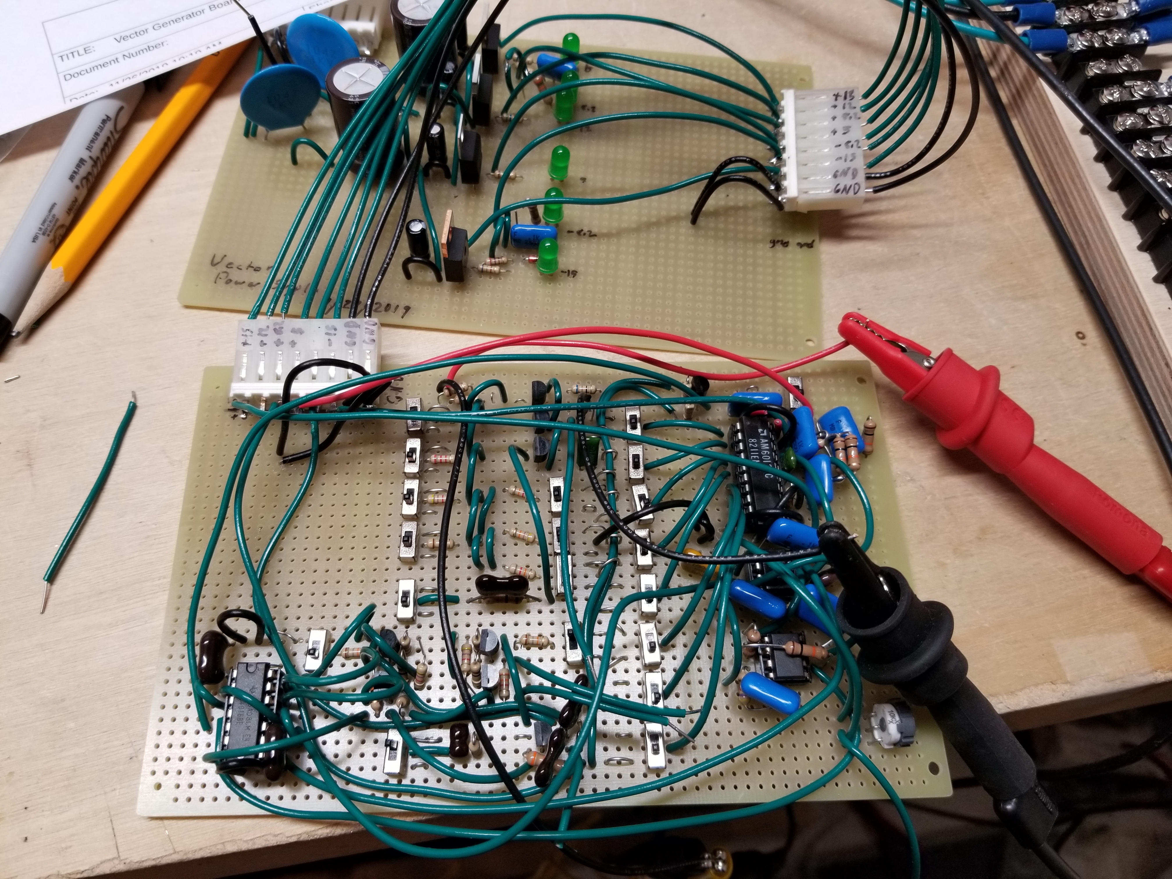
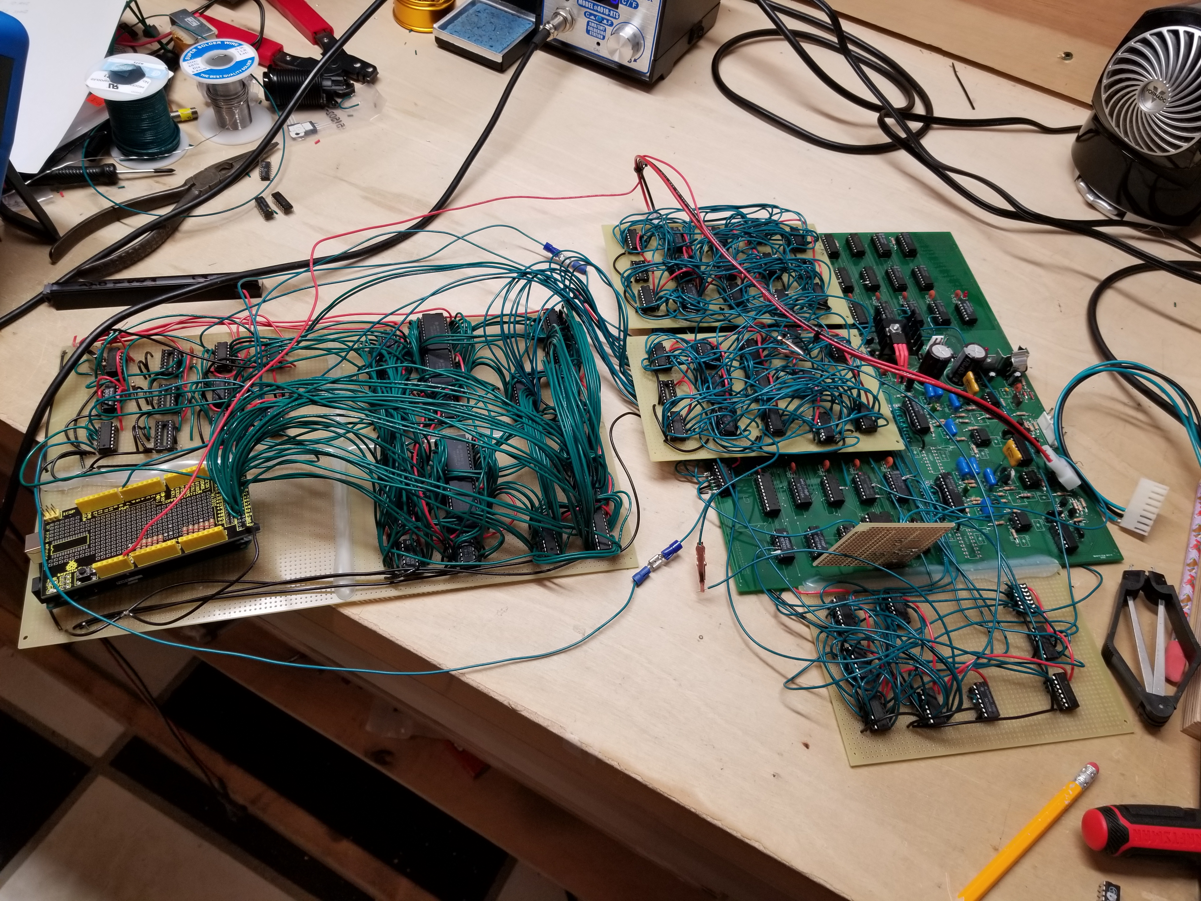
Oddly enough, it seems that I never took any pictures of it just after I populated it with parts. Weird. Anyway, I had to design a double-buffered vector ram board to go with the graphics card to feed it x, y, and z values. I could get away with using an Arduino for it because I just needed it to load the same image into the Vector RAM twice. Here it was, just after being soldered up:
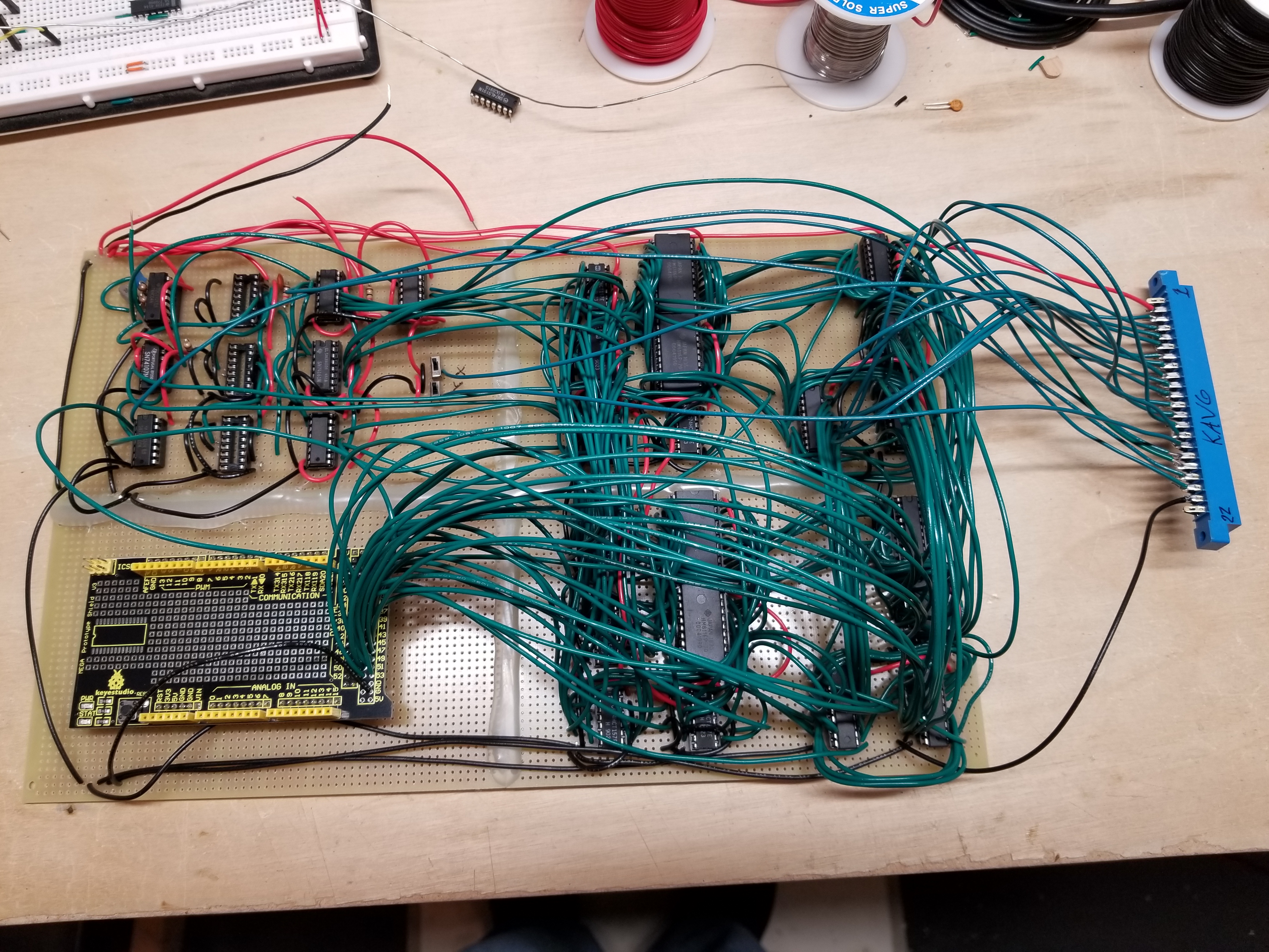
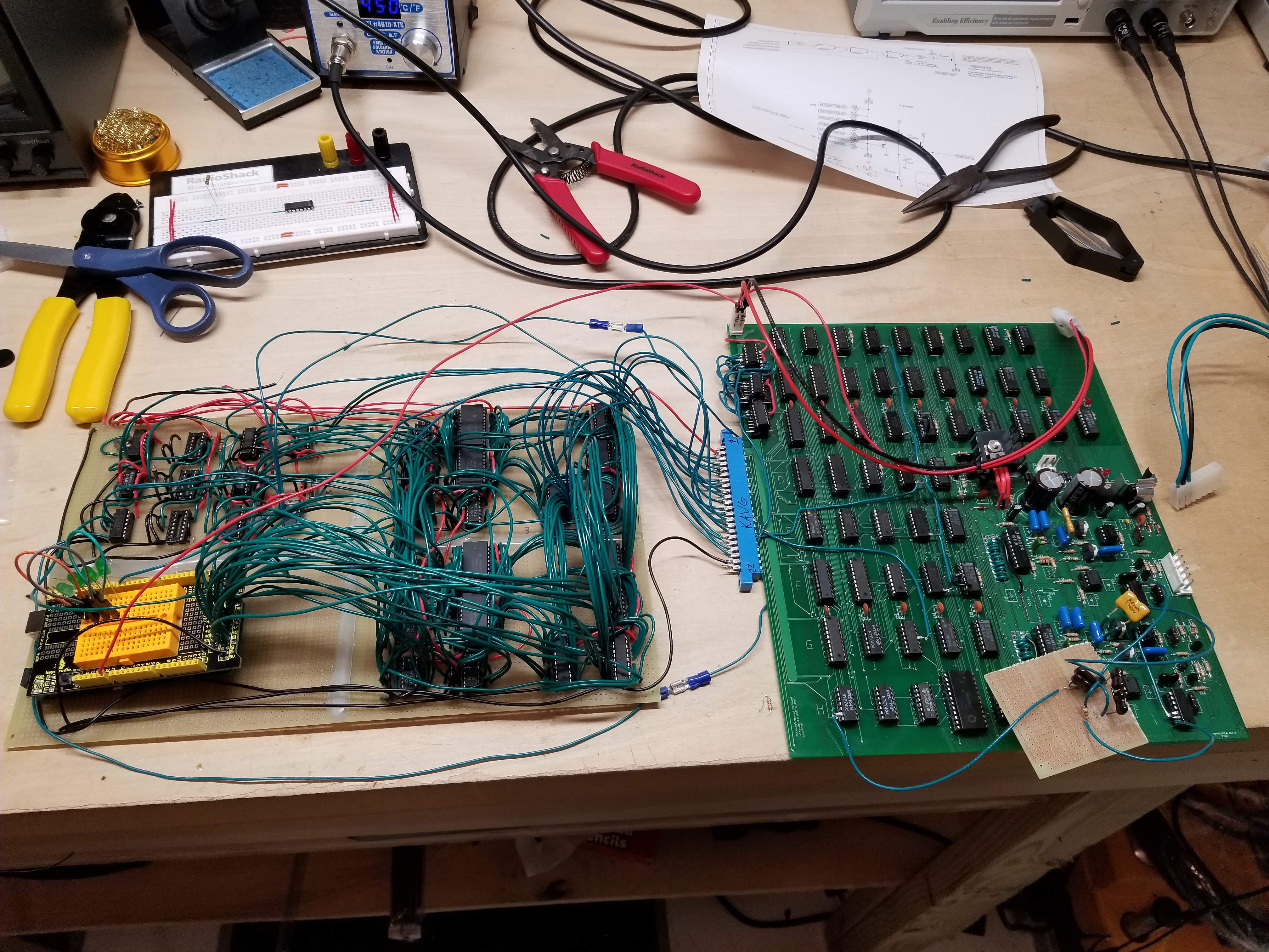
Here it is connected to the graphics card:
I decided that it would be a good idea to plug in the graphics card by itself *just* in case anything blew up. It did not pass the explosion test.
Apparently I grabbed the wrong footprint for the 7915 regulator, which had the input pin swapped with something. Anyway, it went all barbeque on me and I unplugged the board.
I had to do a lot of cut-and-jumpering just to get the thing to work. If you look closely at the pictures below, you can see what I mean. There was about the same amount of wires on the backside, too. In the end, it worked:
It worked, but it still had issues. That didn't stop me from doing a happy dance and whooping it up.
Testing it in the Cabinet
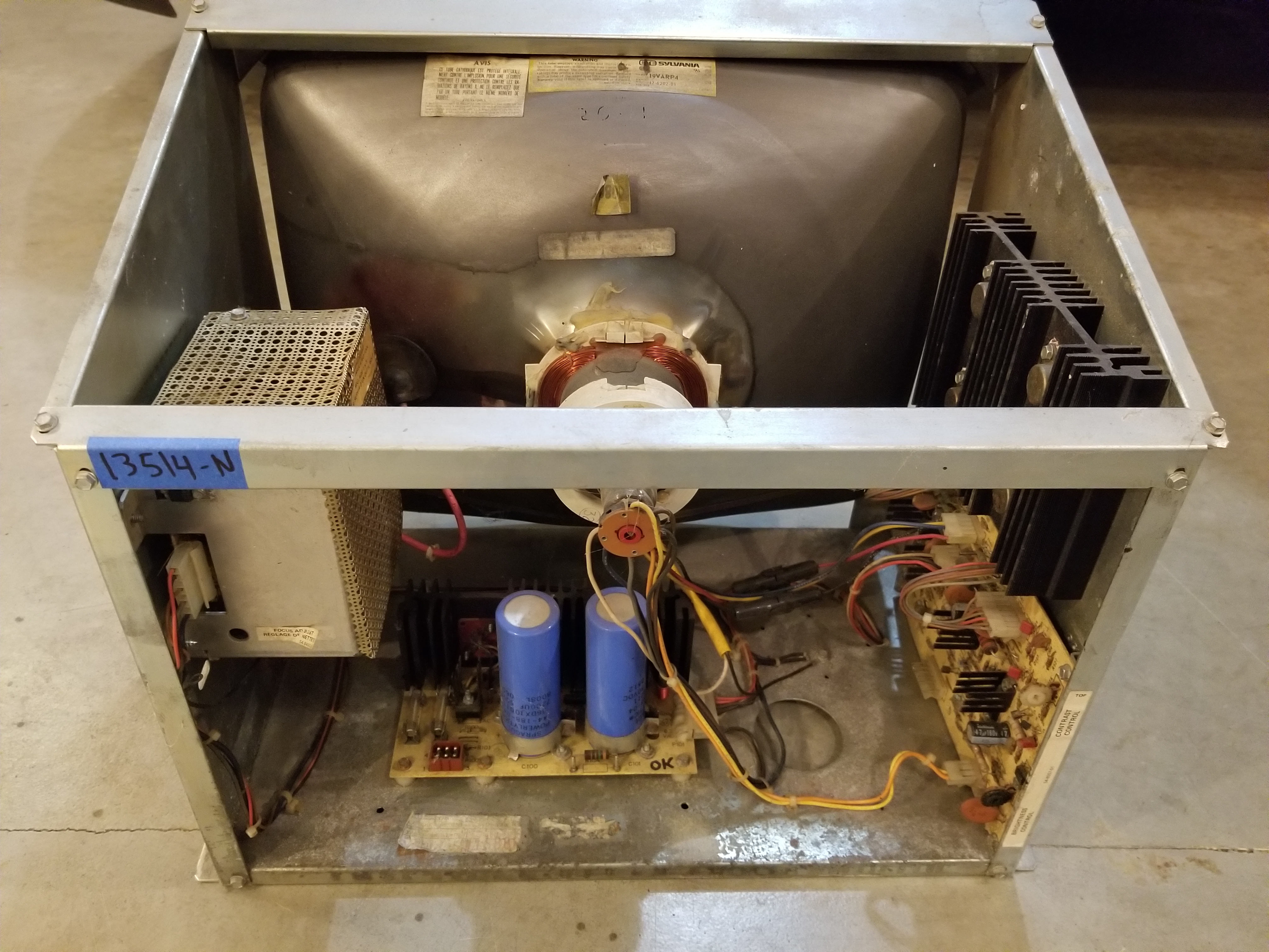
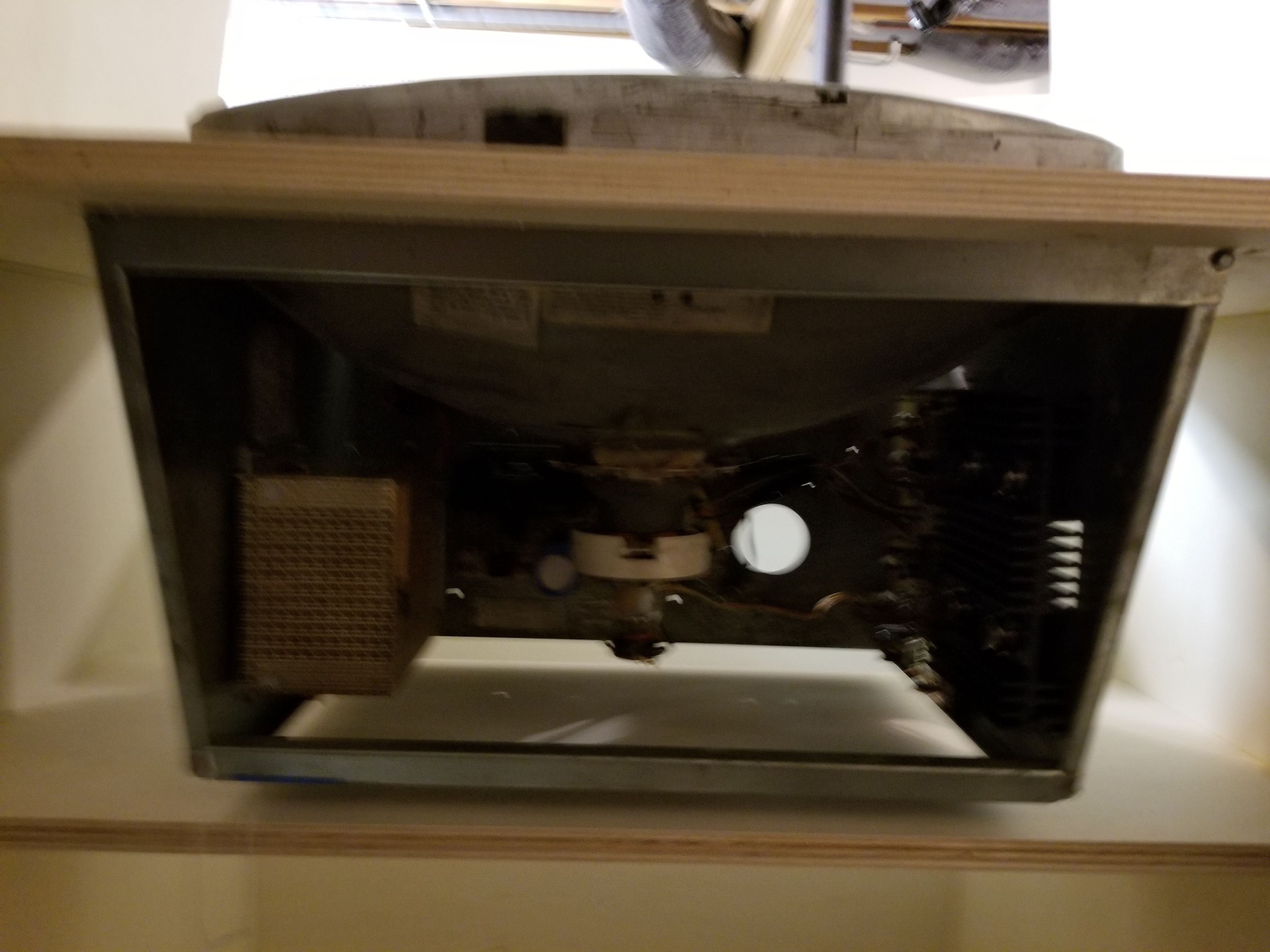
It's one thing to look at a vector game through your oscilloscope, and it's another to see it on an actual monitor. So, I began to wire up the cabinet. I had bought an Asteroids transformer assembly off Sarah to supply the monitor voltages, and I figured I might as well replace Big Blue:
This is what the inside of the cabinet looked like:

After confirming everything was good on my oscilloscope, I powered it on:

Oof. Those are some disgusting vectors.
From looking around on my oscilloscope, it looked like I was having issues with my sample-and-hold. When I originally prototyped it, I could not get it to swing between +/- 8 volts like the manual said it should, so I copied and modified the video inverter circuit to be the sample-and-hold. Obviously, it wasn't doing so well. I soldered up the Atari sample-and-hold, and it worked better:
If you look closely at the monitor output, you can see that not all of the vectors are drawn correctly. Specifically vectors with a negative delta x or delta y or both. As it turned out, I made a bit of a major mistake on the circuits that do the binary subtraction for the equation that finds the slope (y2-y1)/(x2-x1). There is a trick to perform binary subtraction with adders. To do A-B, you invert B, add it to A, and add 1. However, that only works if A is greater than B, which is not the case if the beam has to move left or down. It would be difficult to fix that later...
At this point, the school exhibition was coming up fast, so I began to work on a basic Spacewarz game to demonstrate my hardware. I made a quick control panel so I could start testing code. I totally didn't copy the control scheme on Asteroids...


It only took about a week to program the game since I am pretty good with programming an Arduino. Here's a couple of videos of my Dad and I playing it:
As you may have noticed, there are also some pretty major graphical glitches that appear when things move. I am pretty sure it has something to do with the Arduino program being too slow to write data to the Vector Ram. Maybe I made a mistake with my bitwise operations. I'm not sure.
Fixing the Subtraction Mistake
After the schoolyear ended, I had time to finish up the vector graphics card. I started by coming up with a fix for the subtraction issues. I managed to shove it all onto an oops board that would plug into the space where the 7483 adders would go. I had to make one for the X, and one for the Y.
As you can see, I had to make a lot of changes to that prototype board. This is why we always prototype things before we order PCBs.
Here's what the screen looked like after I got the subtraction fix working:

I had to make plenty of tweaks to the design after that. Eventually, I corrected the overscan (those little loops), and some invisible lines that would overdrive the monitor if I had the picture adjusted to full size. That is why all of the early pictures show the y-axis only using half of the monitor. But that would soon change...
The Second Revision Graphics Card PCBs
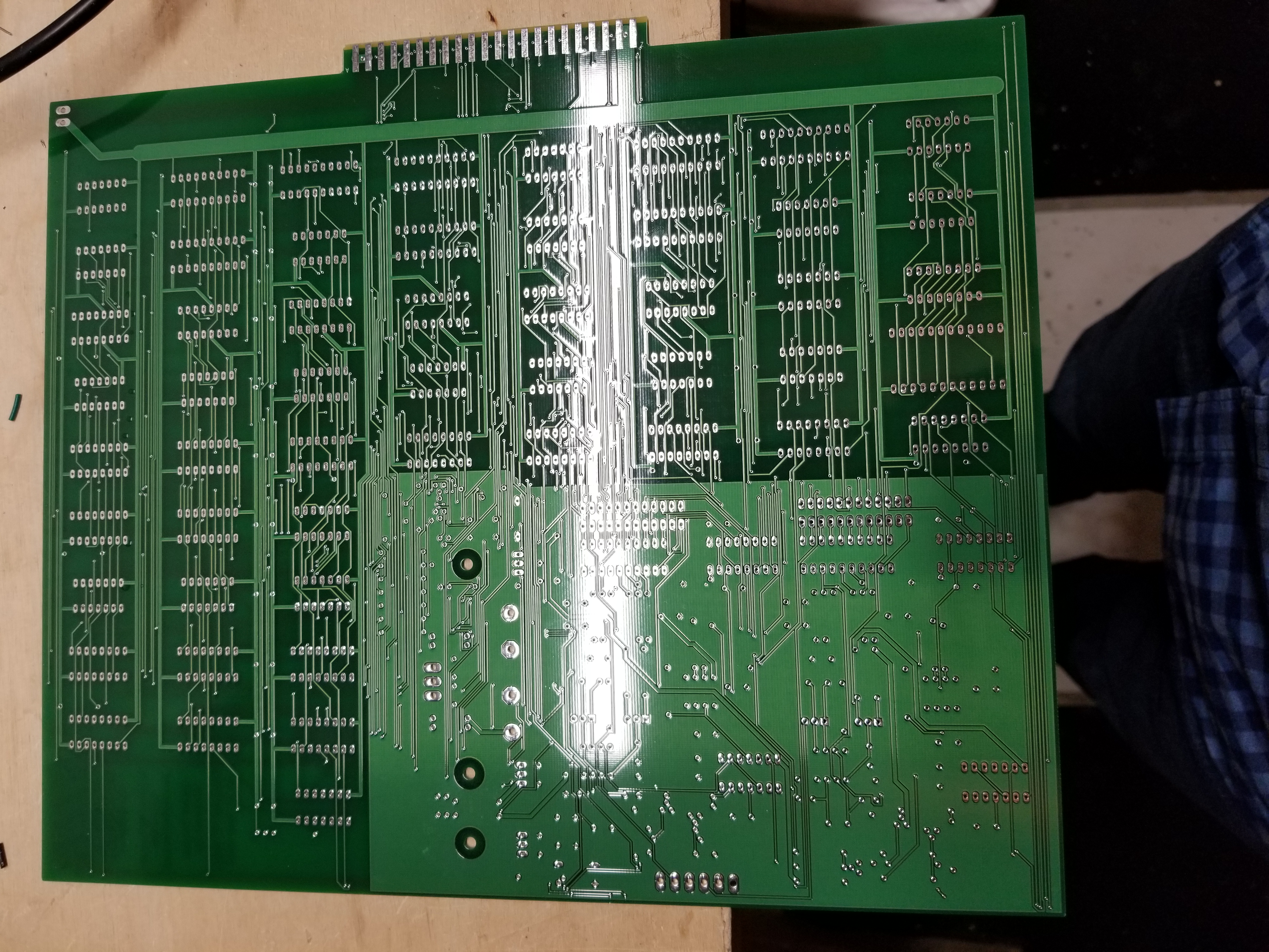
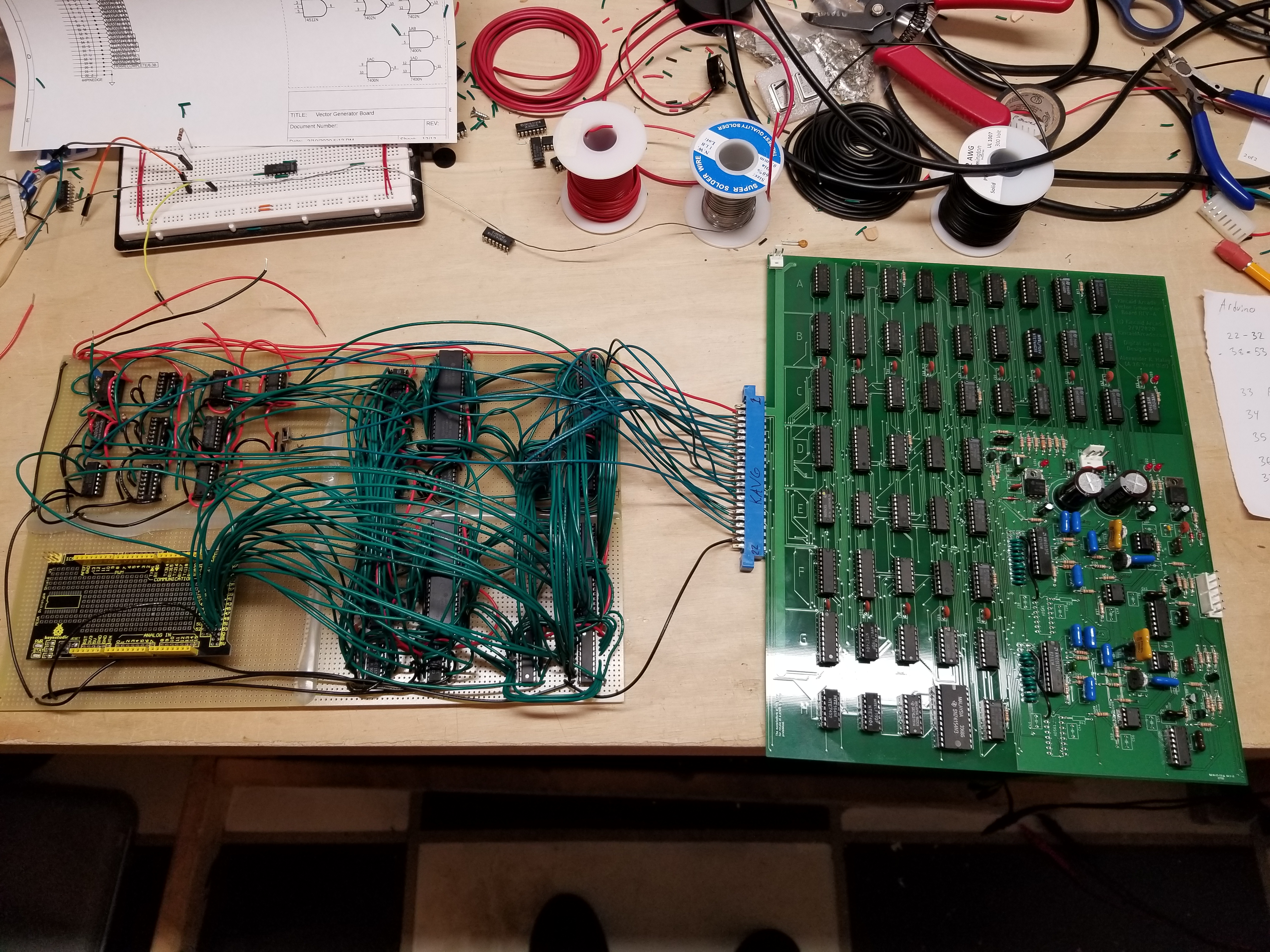
...because I had designed up the second revision of the Vector Graphics Card PCB, as well as some other boards. Here's what they looked like:
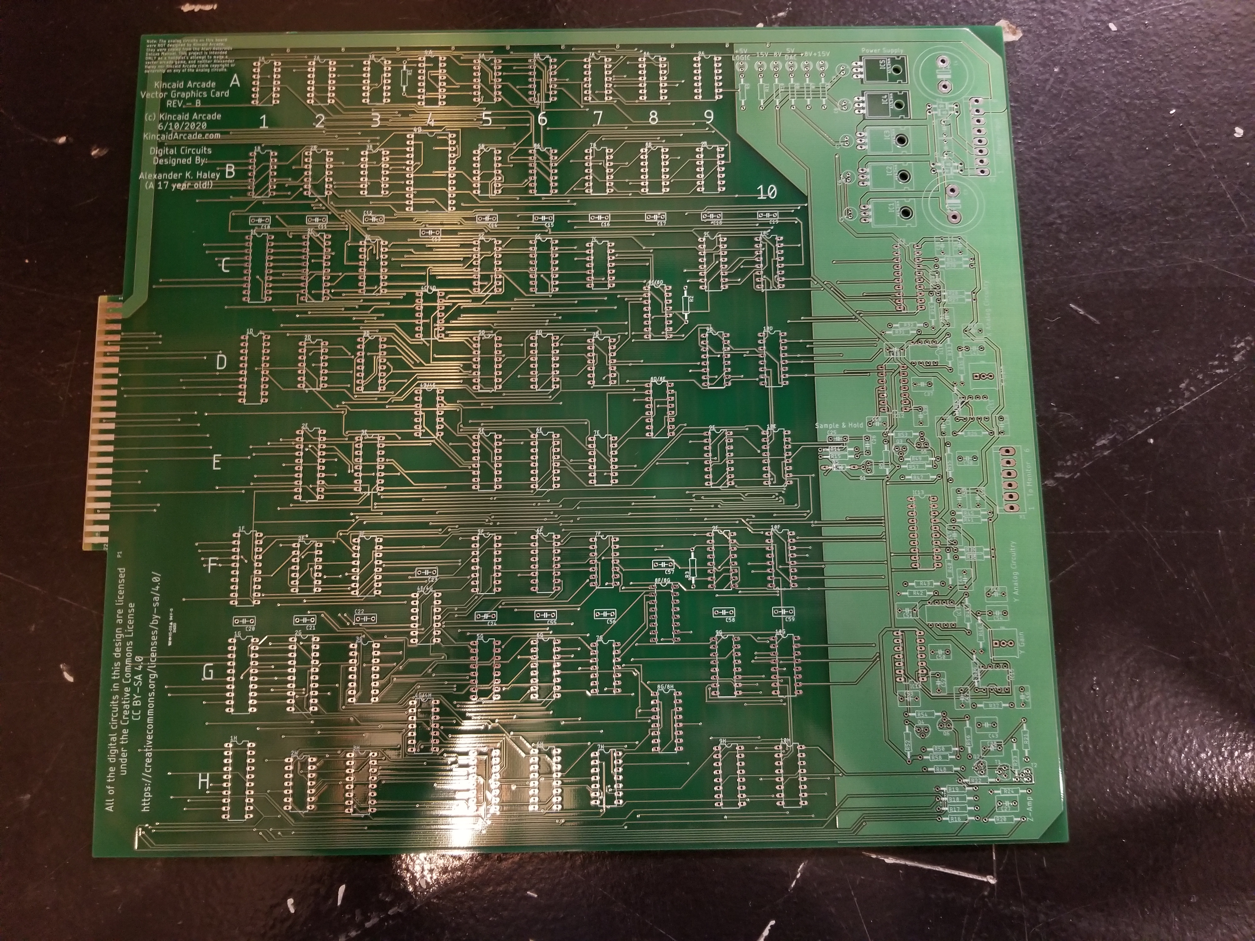

The second revison graphics card.
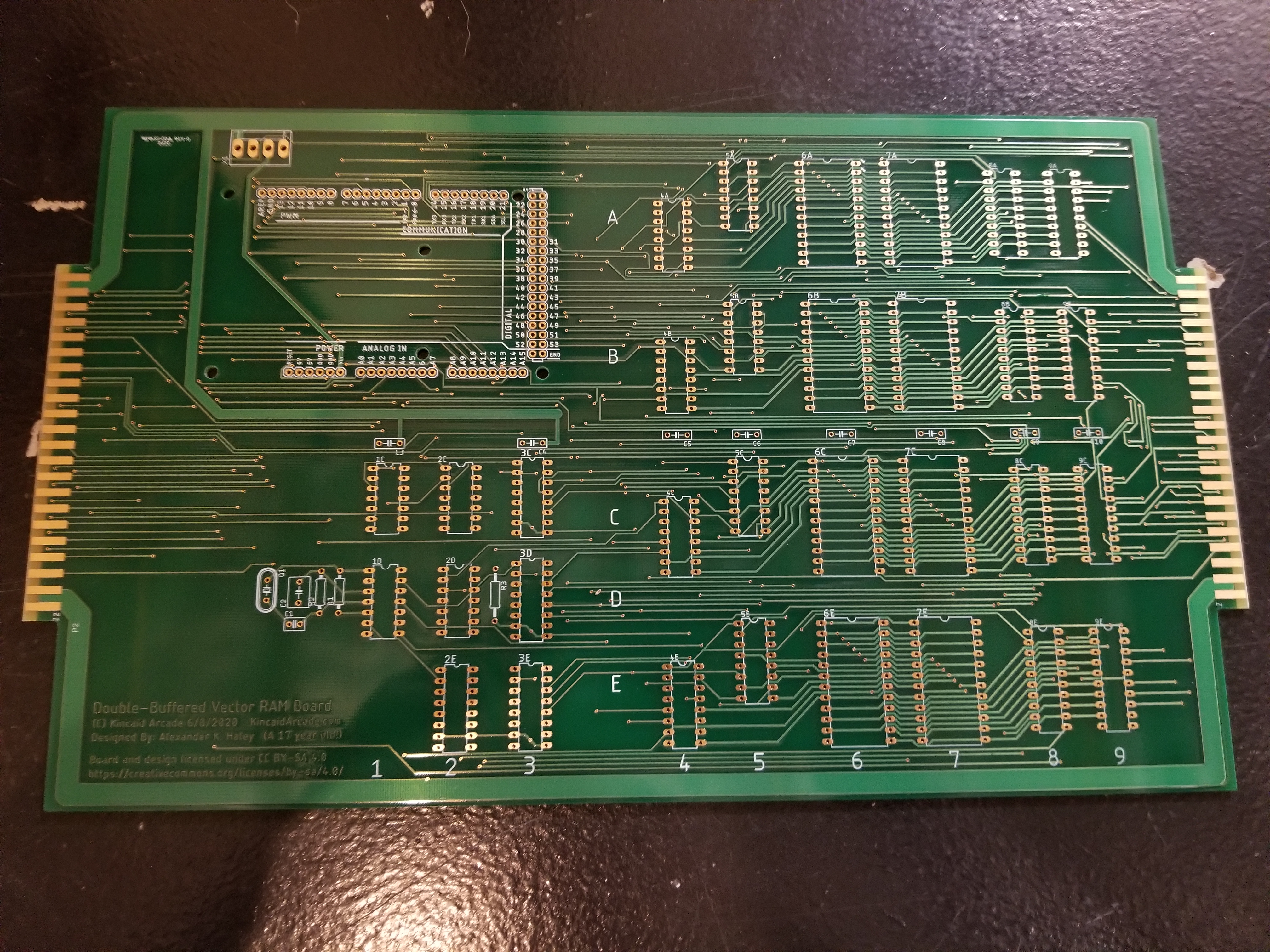

The double-buffered Vector RAM board. It appears they ran out of HASL.

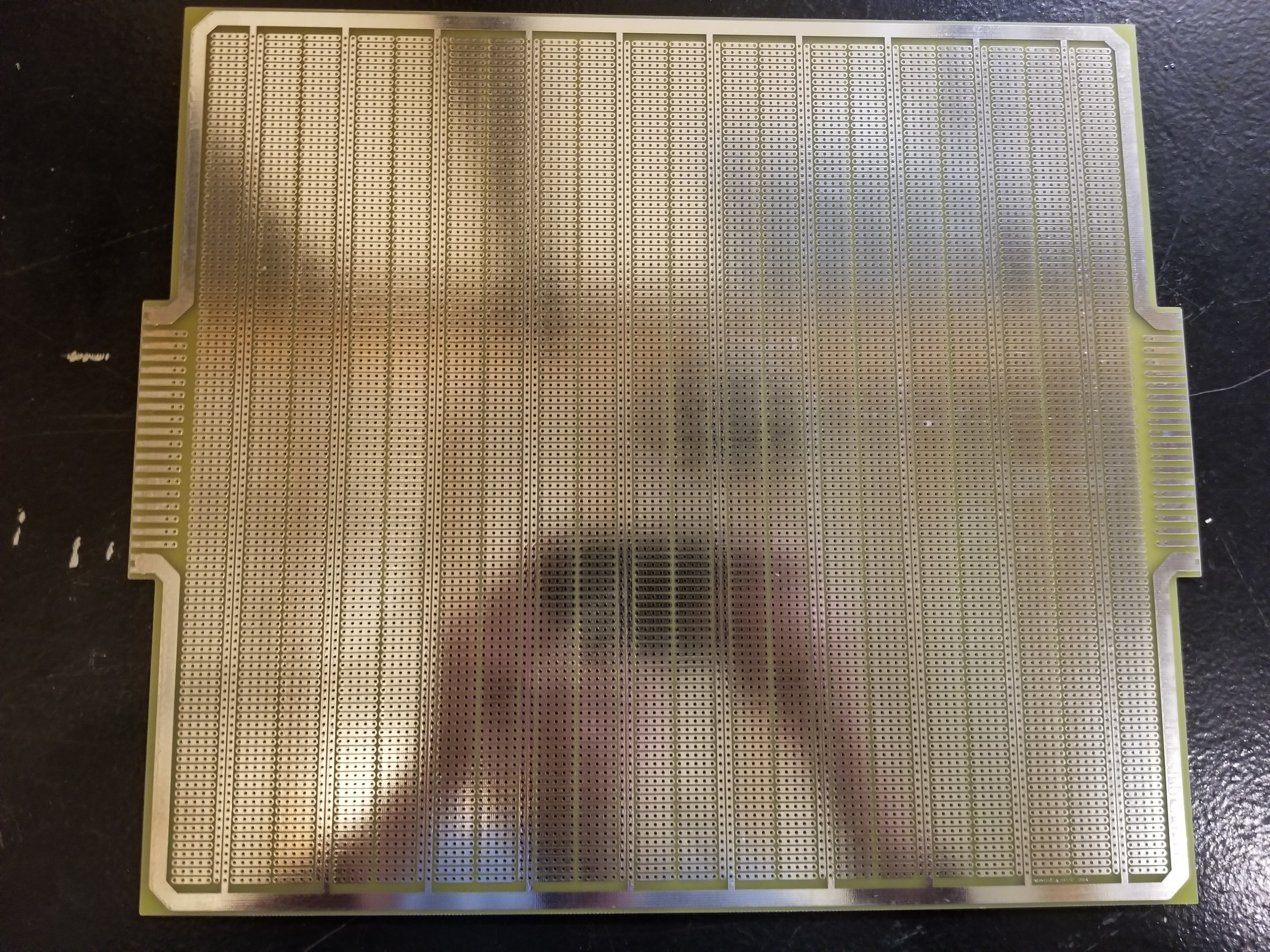
And a massive prototyping board that I was planning to use to prototype the processor. Alas, that won't be happening soon.
It only took several hours of listening to Switchfoot to solder up the circuit boards. Here they were after being populated with parts:
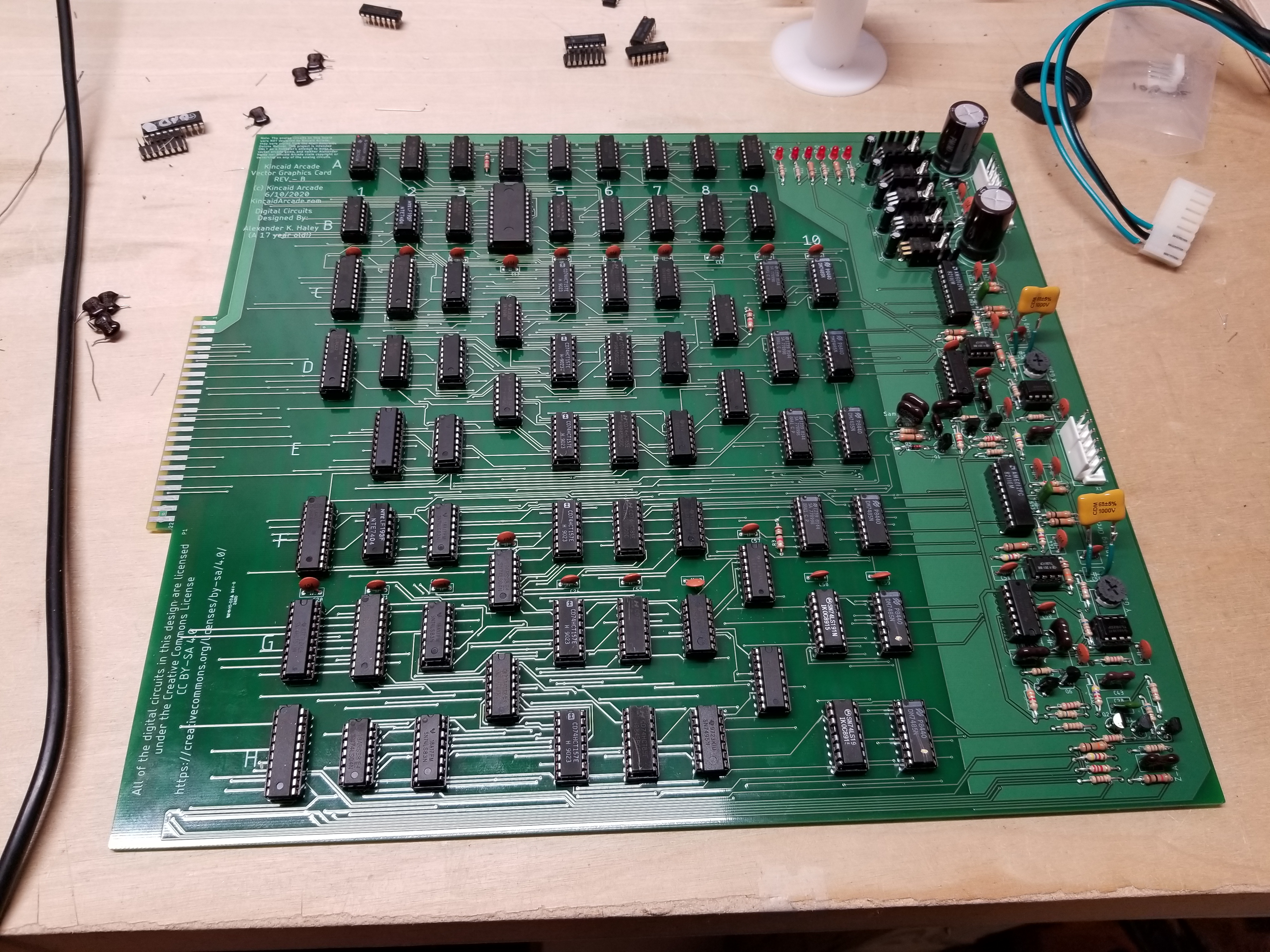
The graphics card.
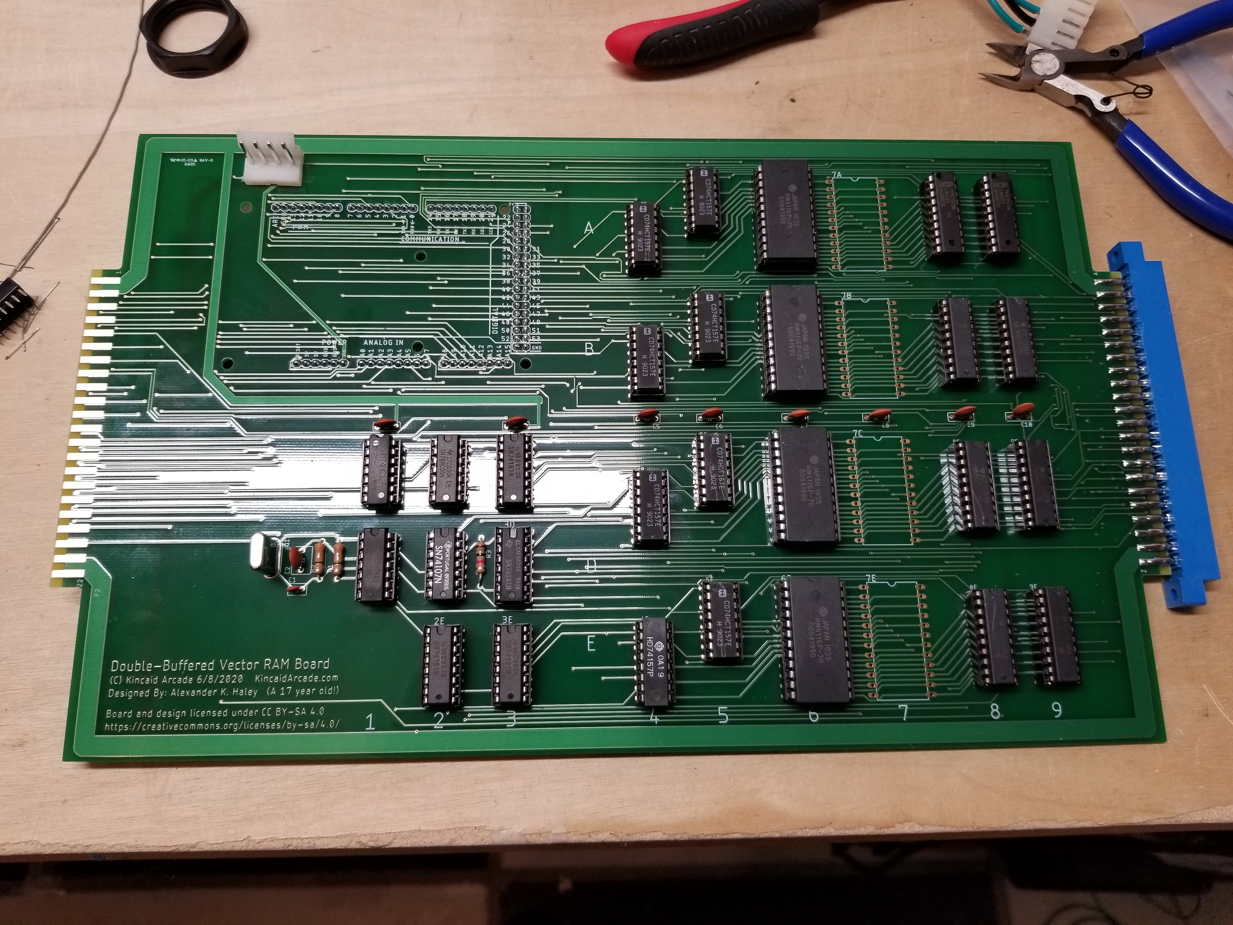
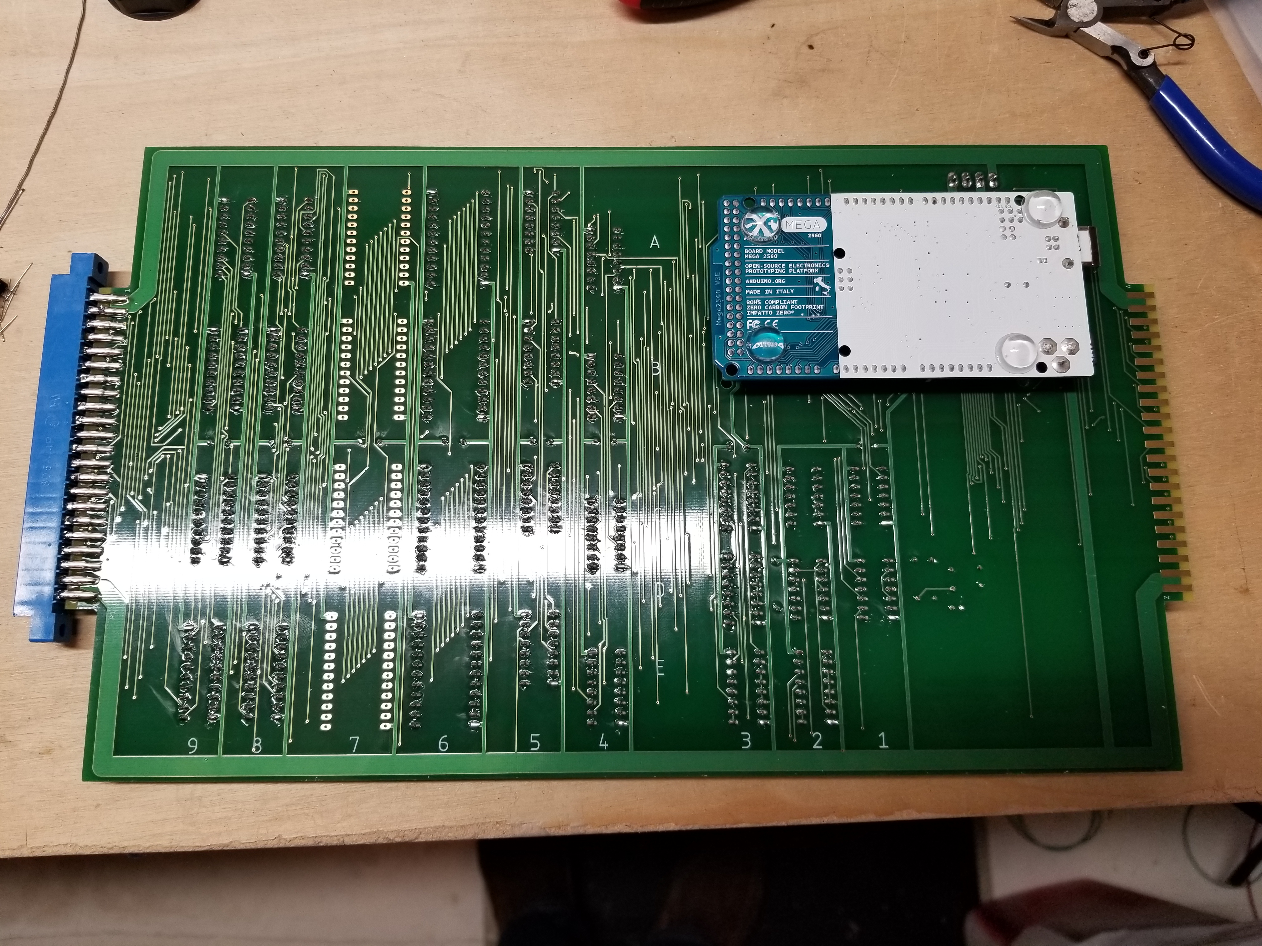
And the double-buffered Vector RAM board. I forgot to mirror the footprint for the Arduino, so I had to mount it upside-down...
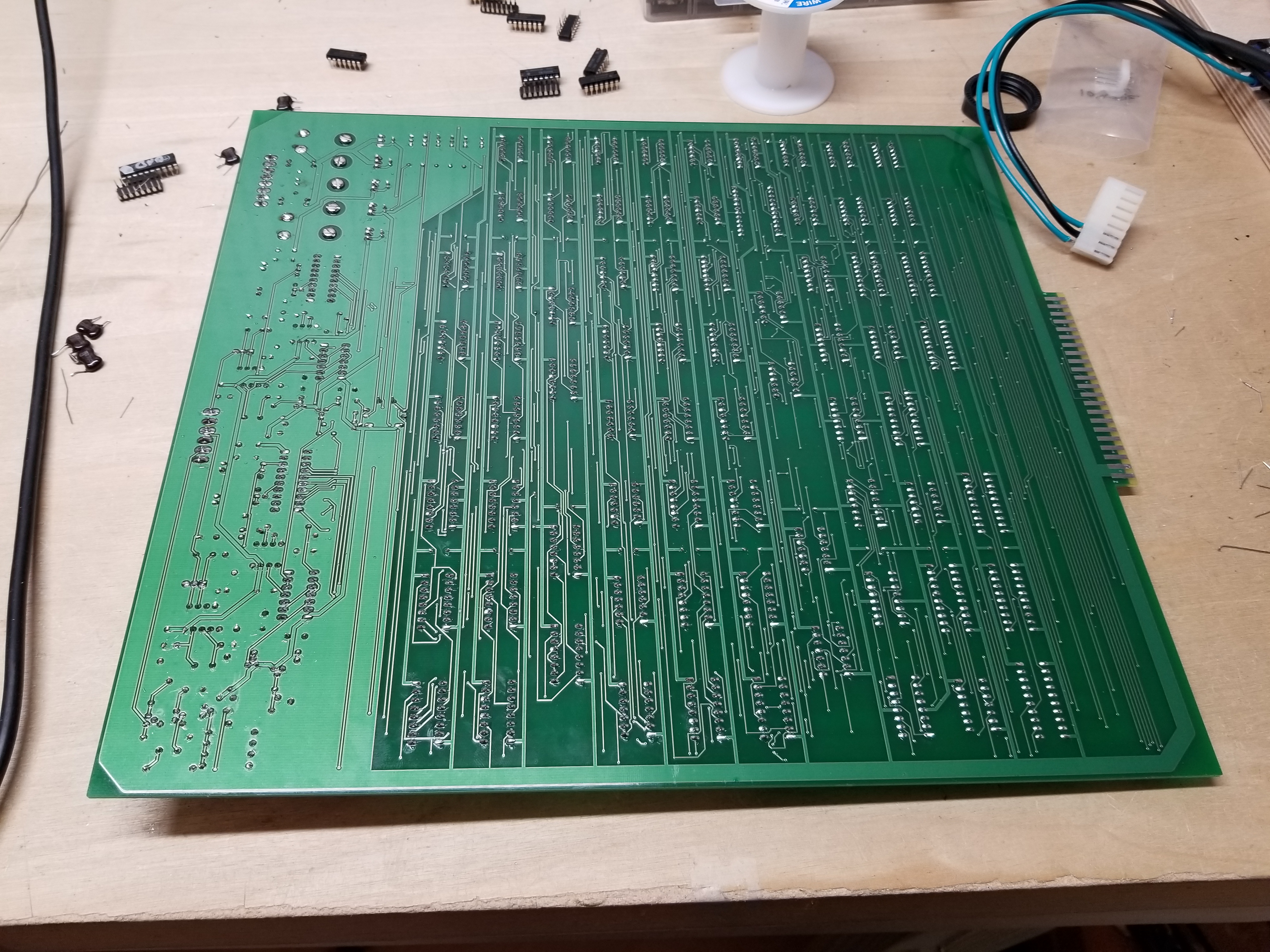
As usual, nothing worked the first time, and I had to make some wire mods on the circuit board for the graphics card. In the end, it worked, and boy did it work well:
All in all, this was a pretty fun project. I hope to be able to design the 16 bit vector processor for it after college. Then I'll be able to program my hit game and make lots of $$$ selling these as conversion kits on KLOV. :)
In the meantime, I've released this project's design files under CC BY-SA 4.0, if anyone is interested. Check it out on the Downloads page!
Does Anyone Know why my Vectors "Fizzle"?
This problem has perplexed me for a while now. As you can see in the video below, the vectors seem to fizzle on my monitor. My vector generator is a literal 1:1 copy of the one in Asteroids Deluxe, but as far as I can tell, neither Asteroids Deluxe (nor any Atari Vector) has this fizzle as the lines are drawn. At first I thought it was because I was running the Vector Generator at 2.5mhz instead of 1.5mhz, but running it at 1.5mhz didn't change anything.
It shouldn't be a problem with the monitor, because it has done the fizzle with all my prototypes, but it never showed any fizzle when hooked up to an Atari Lunar Lander machine.
If anybody has any insight, please let me know!
This is on a G05-801 monitor with a 60hz refresh rate.
This page was published 8/30/2020
This page was last edited 1/5/2022
Spelling, grammar, and readability corrections.